Sole configuration for metal wood golf club

a golf club and sole technology, applied in the field of golf clubs, can solve the problems of golf ball flying short of the intended target, low golf shot, loss of club head speed, etc., and achieve the effect of increasing the effective bounce of the club head, less friction, and increasing the speed of the club head

Inactive Publication Date: 2007-05-03
RIFE GUERIN D
View PDF12 Cites 28 Cited by
  • Summary
  • Abstract
  • Description
  • Claims
  • Application Information

AI Technical Summary

Benefits of technology

[0005] The present invention is a metal wood type golf club head of conventional design with an improved sole configuration to increase the effective bounce of the club head. The bottom sole surface is formed in separate sections. A first forward sole section is located directly behind the leading edge of the club head and extends partway to the rear of the club head. The forward sole section is formed of a generally flat or planar land area at an angle downward from the horizontal when the club head is in a normal address position just prior to the execution of a golf shot. This angle is the bounce angle and raises the leading edge above the ground surface. The forward section provides a frictional surface that impacts the ground as a golf ball is hit with the club head. The bounce angle of the forward section prevents the club head from digging into the turf or ground and actually causes the club head to bounce. The bottom sole includes at least a second section behind the forward sole bounce section. The second section extends upwardly and inwardly and recesses into the club head body so it is raised above the ground surface with the club head at the address position. There is less friction on the second section surface since it is raised relative to the ground as a golf ball is hit by the club head. The raised second section preferably has an aerodynamic or airfoil shape that traps air between the bottom sole and ground creating lift and increasing club head speed.
[0006] Another feature of the sole structure is increased mass low on the club head because of the increased surface area and thickness of the metal wood shell in the lower areas. This produces a higher trajectory ball flight for a given loft angle of the clubface. This, in turn, allows for a lower loft angle for a given ball flight resulting in increased distance for a given swing force. Because of this combination of bounce, loft angle and lower weight, lower lofted clubs, such as drivers, may be used in the fairway resulting in longer golf shots for a given swing force.
[0007] In various embodiments, the club head may be provided with a rear edge of the bottom sole that rests the club head on the ground for increases stability. The club head may have a flat mid section to stabilize the club at address. Similarly the bottom sole of the club head may have a forward or bounce section of various sizes and bounce angles.

Problems solved by technology

This is particularly true when more severe conditions are encountered, such as extremely hard or soft surfaces.
For example, when a golf club impacts a hard surface, the club head will tend to bounce resulting in the golf ball being hit thin resulting in a lower golf shot.
When a ground surface is soft, a golf club may embed in the ground resulting in the loss of club head speed causing the golf ball to fly short of the intended target.

Method used


Image

  • Sole configuration for metal wood golf club
  • Sole configuration for metal wood golf club
  • Sole configuration for metal wood golf club

Examples


Embodiment Construction

[0026] Detailed embodiments of the present invention are disclosed herein. It should be understood that the disclosed embodiments are merely exemplary of the invention, which may be embodied in various forms. Therefore the details disclosed are not to be interpreted as limiting, but merely form a basis for the claims and as a basis for teaching one of ordinary skill in the art how to make and / or use the invention.

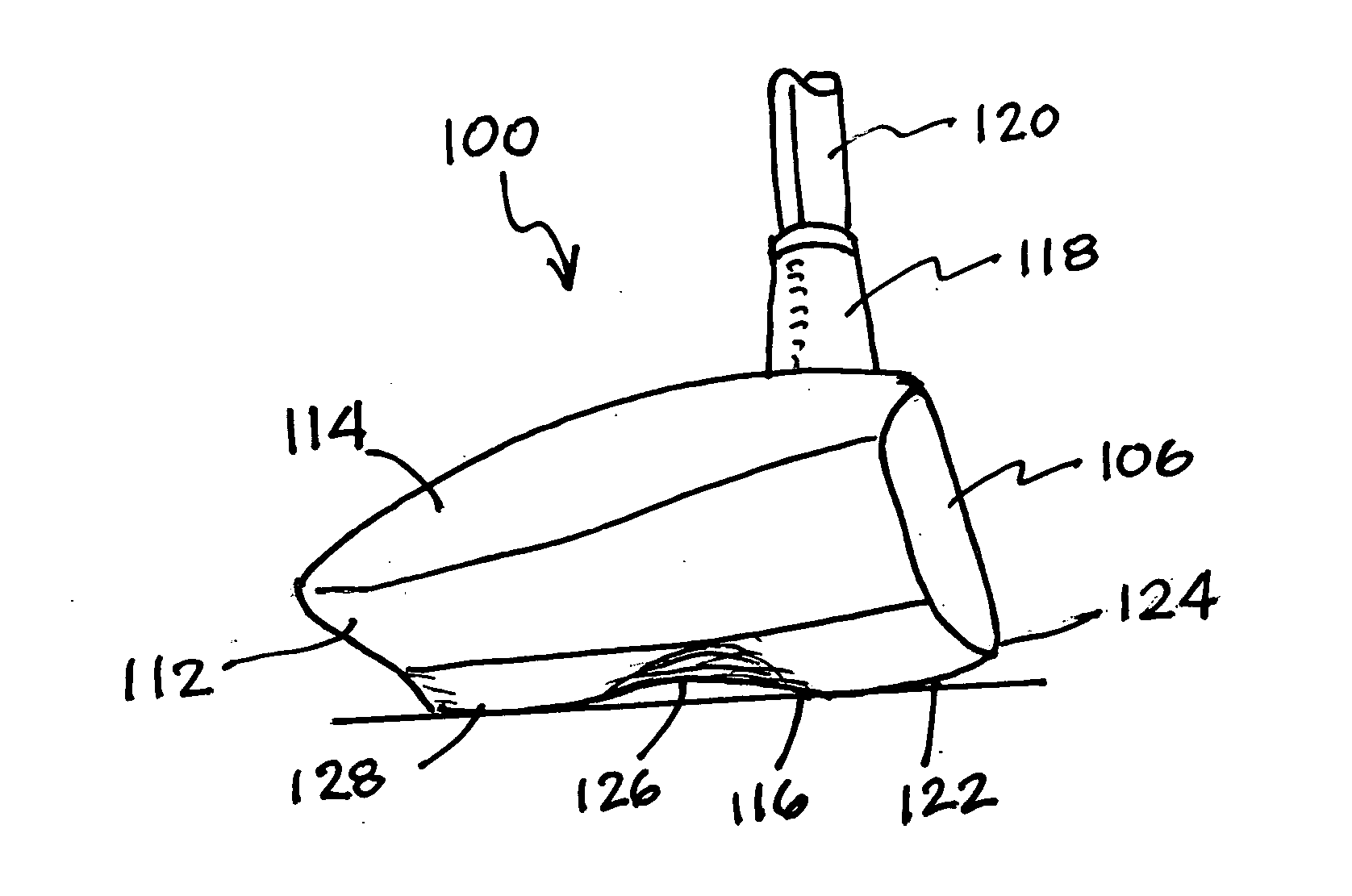
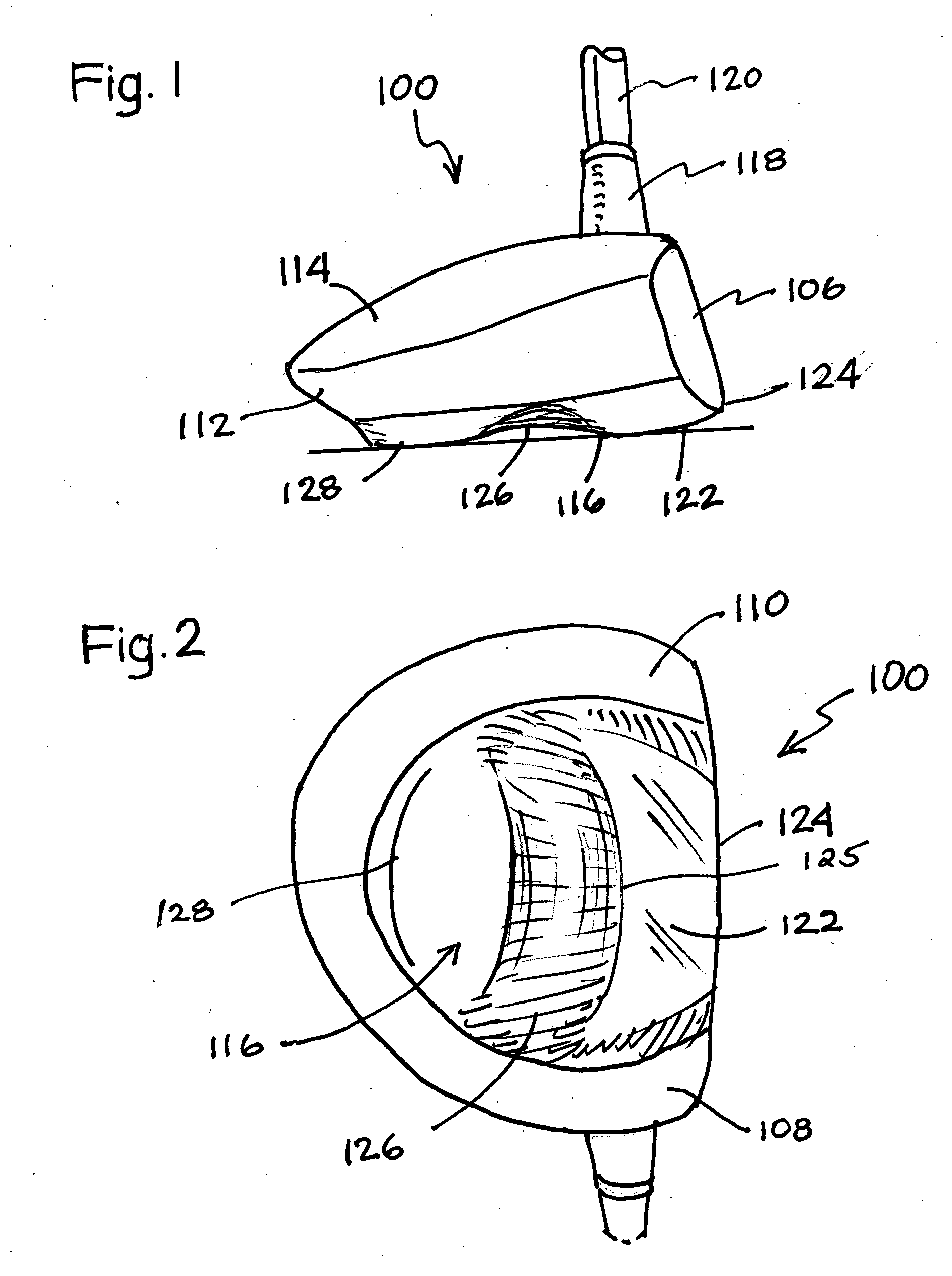
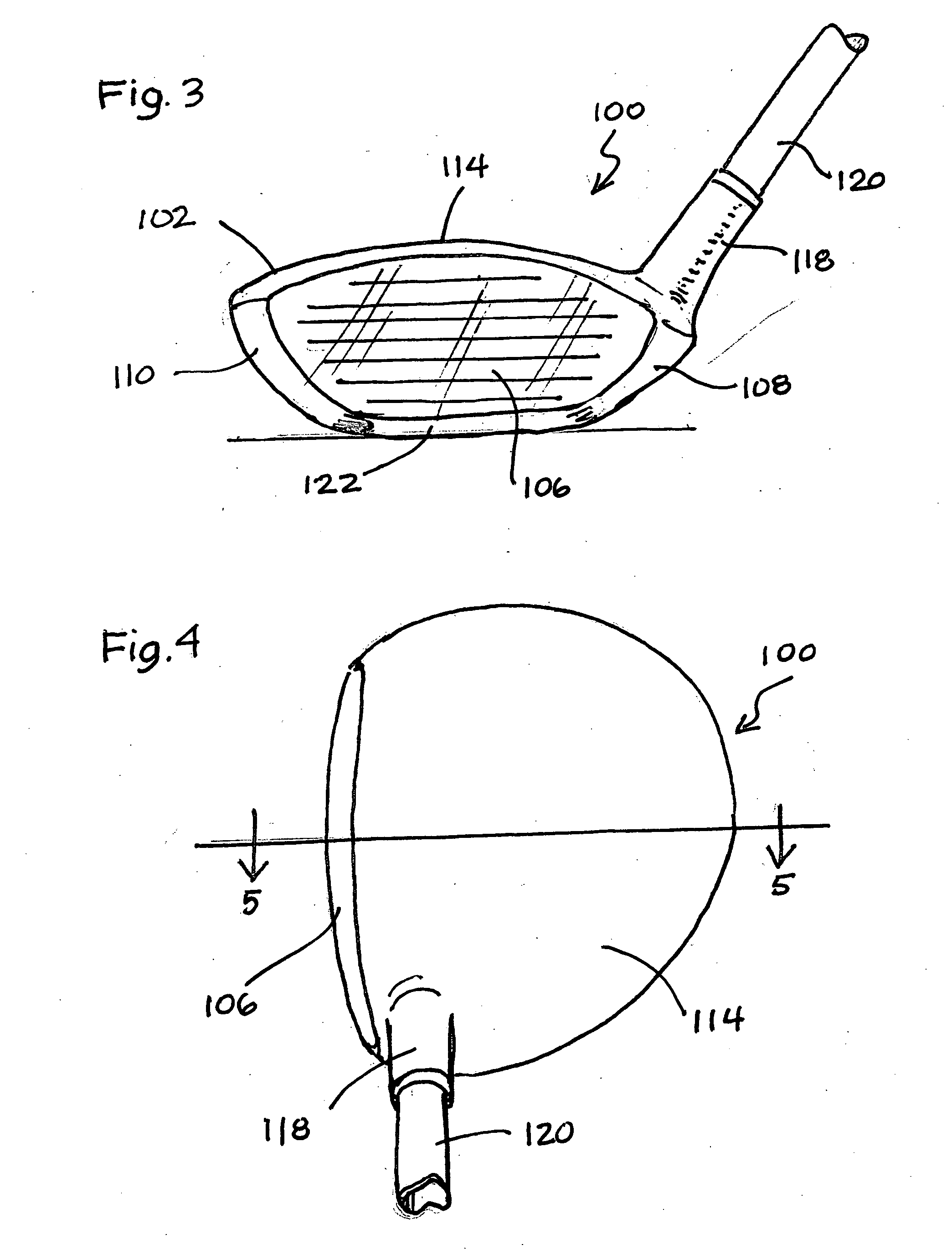
[0027] Referring to the drawings, FIGS. 1 to 5 disclose a metal wood golf club head100 of the present invention formed with a body portion 102 made of a hard metal material, forming a metal shell 104. The club head 100 includes a ball striking face 106, heel 108, toe 110, rear face 112, top crown 114, and bottom sole 116. The club head 100 is preferably formed with a hosel 118 connected to a conventional shaft 120 of any suitable length and handle or grip (not shown) on the upper end thereof.

[0028] The bottom sole 116 is formed in separate sections. A first forward sole s...


PUM


Abstract

A metal wood type golf club head including a club head body and means for attachment to a golf shaft, the club head body including a frontal ball striking face having a center of percussion thereon, a rear face, a heel, toe, and top crown, and a bottom sole having a forward section and at least one additional rear section. The forward section provides a friction surface and is defined by a bounce angle extending downwardly from said frontal ball striking face to prevent the leading edge of the club head from digging into the turf or ground during the execution of a golf shot. The rear section of the bottom sole is a reduced friction surface and is recessed upwardly into the club head.

Description

BACKGROUND OF THE INVENTION [0001] The present invention relates to golf clubs and in particular to wood or metal wood type golf club heads having an improved sole configuration. [0002] The way the sole of a golf club impacts the ground surface during the execution of a golf shot often determines the ball flight and the overall results of the shot. The leading edge of a golf club head is the edge at the interface of the bottom sole and lower portion of the ball striking face. It is well known in order to prevent the leading edge from digging into the ground at impact with a golf ball, the bottom sole configuration is formed with a downwardly extending, angular surface toward the rear edge of the club head that raises the leading edge above the ground. This is known in the art as the bounce of the club head, the bounce angle being the angle of the bottom sole relative to the horizontal when the club head is in a normal address position prior to the execution of a golf swing. Therefor...

Claims


Application Information

Patent Timeline
Patent Type & Authority Applications(United States)
IPC IPC(8): A63B53/00
CPCA63B53/0466A63B49/06A63B2225/01A63B2053/0433A63B60/52A63B53/0433
Inventor RIFE, GUERIN D.
Owner RIFE GUERIN D
Why Eureka
Try Eureka