Endoscope apparatus

Active Publication Date: 2007-05-03
OLYMPUS CORP
13 Cites 51 Cited by

AI-Extracted Technical Summary

Problems solved by technology

Therefore, in a structure according to a conventional technology, an increase in the amount of change i...

Method used

[0118] By using the bias-applying coil spring 61, a force acting in a direction opposite to a direction in which the movable lens 34 is moved due to the phase transition of the shape memory element 41, is exerted on the movable lens 34. Accordingly, it is possible to increase the speed at the time of transition of the shape memory element 41 to the original phase. Therefore, a driving speed of the movable lens 34 is increased.
[0120] Moreover, it is desirable to use a non-conductive (insulation) tube 51, when the shape memory element 41 is to be transformed by heating by energizing. Accordingly, when being energized (when the electric power is supplied), the shape memory element 41 does not have electrical influence from outside or from within the shape memory element 41. Therefore, it is possible to drive the shape memory element 41 efficiently. Moreover, as a matter of course, a method for heating the shape memory element 41 is not restricted to energizing by electric power, and may be any other method.
[0123] By the connecting member 38 maintaining the gap from the groove 37 of the movable lens frame 35, even when an axis in a driving direction of the movable lens frame 35 and an axis in a direction of change of shape of the shape memory element 41 are misaligned by a small amount, the gap absorbs the misalignment. Therefore, it is possible to prevent a decline in a driving speed, or stopping of driving due to hitching of the movable lens frame 35.
[0124] In other words, due to the gap, even when an axis in a direction of movement of the movable lens 34 which is determined by the lens barrel 7, and an axis in a direction of deformation by heating of the shape memory element 41 do not coincide perfectly, it is possible to perform the drive smoothly. Moreover, although it is not shown in the diagram, the groove 37 may be formed around the entire outer circumference of the movable lens frame 35. In this case, even when the connecting member 38 is shifted in a direction vertical to the driving direction of the movable lens 34, it is possible to perform the drive smoothly and efficiently.
[0129] In the third embodiment, due to the stoppers 39a and 39b, a driving area (driving range) of the movable lens frame 35 is limited, and it is possible to perform accurately a position control at least at two points, by a simple mechanism. Moreover, when the bias-applying coil ring 61 is there, when the movable lens frame 35 is not being driven by a change in the shape of the shape memory element 41, it is possible to hold by the stopper 39a. As a result of this, it is possible to perform an accurate position control by a simple structure.
[0133] In the fourth embodiment, for preventing the overload from being exerted on the shape memory element 41, the structure is such that an amount of displacement equal to a length of the contraction of the shape memory element 41 is absorbed by the contraction of the buffering coil spring 62.
[0135] From a point of view of a structure of the movable lens frame 35 of the optical mechanism, for example in the state in which the drive is stopped forcibly by the abutting of the movable lens frame 35, when the shape memory element 41 is supported by a length shorter than the change in length of the phase transition of the shape memory element 41 due to the heating, the overload is exerted on the shape memory element 41. As a result of this, the life of the shape memory element 41 is shortened. In the fourth embodiment, it is possible to prevent the exerting of the overload on the shape memory element 41 by absorbing the change in length of the amount of the change in length of the phase transition, by the buffering coil spring 62. Furthermore, it is possible to convert a substantial portion of the change in length of the shape memory element 41 to a displacement of the movable lens frame 35.
[0138] The shape memory element 41 is heated by applying the voltage by the energizing unit (not shown in the diagram), and the movable lens 34 is driven. At this time, the both ends of the shape memory element 41 can be disposed at one place. Therefore, an energizing mechanism can be simplified. Moreover, regarding the shape memory element 41, a surface area of the two shape memory elements 41 upon bending is greater as compared to one shape memory element 41 having a cross-sectional area of a diameter same as a total cross-sectional area of two diameters. Therefore, it is possible to drive efficiently by raising up a heat radiation effect with respect to the change in temperature occurred due to the driving. Furthermore, since it is possible to make the diameter of the shape memory element 41 smaller, the endoscope apparatus can be assembled easily.
[0139] Furthermore, in a case of driving the movable lens frame 35 by the change...

Benefits of technology

[0008] The present invention is made in view of the abovementioned issues, and an object of the present invention is to provide an endoscope apparatus which is capable of focusing by using a shape ...

Abstract

An endoscope apparatus includes a front end section which is rigid, and a flexible tube which has a bent portion. One end of a tube which can be bent is fixed to a lens barrel which holds an optical mechanism having a movable section. The tube is extended in a longitudinal direction of the flexible tube of the endoscope apparatus, and at least a part of a shape memory element is accommodated inside the tube. One end of the shape memory element is fixed to an end of the tube, which is not fixed to the lens barrel, and the other end of the shape memory element is mechanically connected to the movable section of the optical mechanism which includes the movable section. Due to expansion (elongation) and contraction of the shape memory element, relative positions of the movable section of the optical mechanism which includes the movable section, and one end of the tube fixed to the lens barrel are changed.

Application Domain

SurgeryEndoscopes

Technology Topic

EngineeringEndoscopy device

Image

  • Endoscope apparatus
  • Endoscope apparatus
  • Endoscope apparatus

Examples

  • Experimental program(13)

Example

First Embodiment
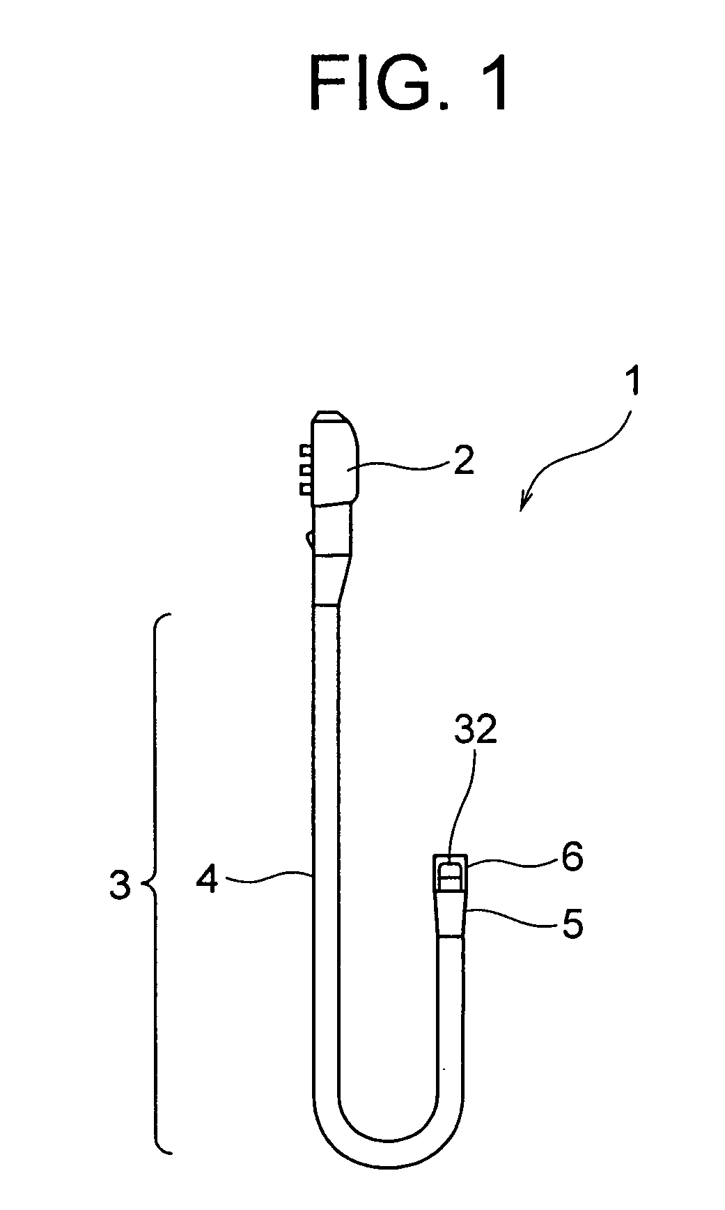
[0104]FIG. 1 shows a schematic view of an endoscope apparatus according to a first embodiment of the present invention. As shown in FIG. 1, an endoscope 1 includes an operating section 2 which performs a bending operation and a control of a pipe conduit system, and an inserting section 3 of which a rear end side is connected to the operating section 2, and which is inserted into a body cavity of a body to be examined.
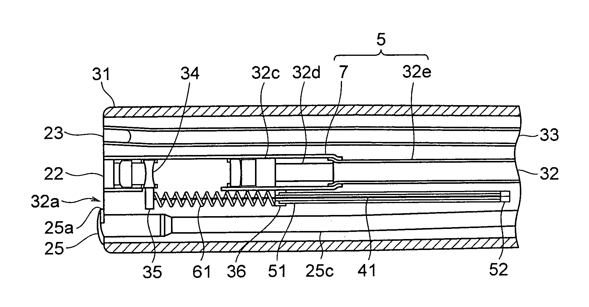
[0105] The inserting section 3 includes a flexible tube 4, a bending section 5 which can be bent, and which is provided at a front end side of the flexible tube 4, and a front end section 6 which is rigid, and which is provided at a front end side of the bending section 5. The front end section 6 includes an imaging unit 32 which is built in, and which takes an image of a portion inside a body cavity which is being observed. The imaging unit 32 will be described later.
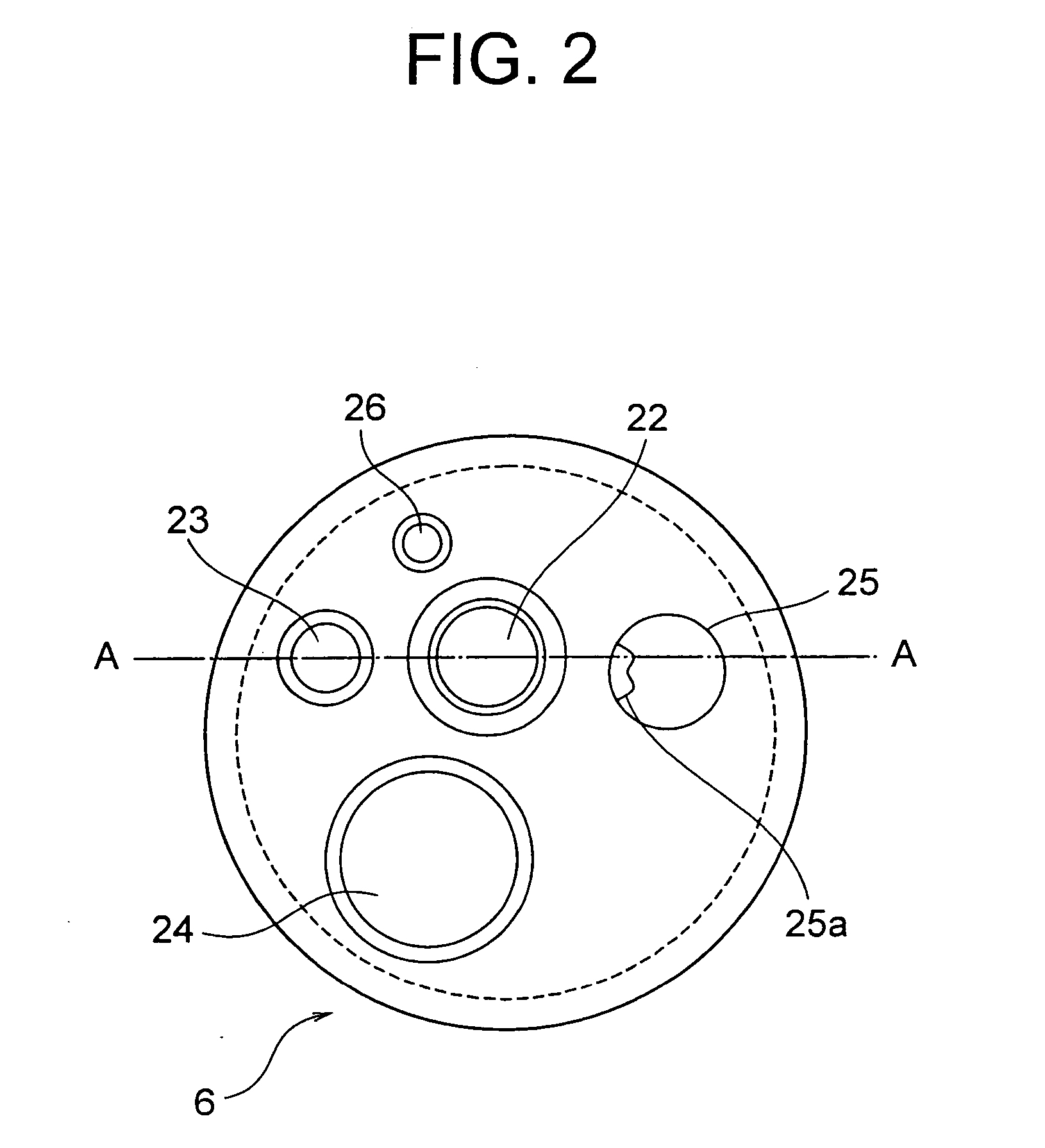
[0106]FIG. 2 shows a front view of an inserting front end section of the endoscope 1 shown in FIG. 1. As shown in FIG. 2, a front end surface 21 of the front end section 6 includes an observation window 22 as a lens, which includes the imaging unit 32, an illumination window 23 as a lens which includes light guiding units, a channel aperture section 24 for inserting an endoscopic instrument, a gas and water nozzle 25 which is an aperture section of a gas and water channel 25a for cleaning the observation window 22, and a channel aperture section 26 which is an aperture section of forwarding water channel for cleaning body fluids such as blood and mucus of a diseased part of a person examined.
[0107]FIG. 3 and FIG. 4 show a cross-sectional view of a front end section to be inserted, along a line A-A in FIG. 2. As shown in FIG. 3, the front end section 6 is provided with a rigid front end section main body. Built-in components such as the imaging unit 32 corresponding to the observation window 22, and light guiding unit 33 corresponding to the illuminating window 23 are installed in the front end section main body. Moreover, the front end section main body is covered by a front end cover 31.
[0108] The imaging unit 32 includes the observation window 22, an objective optical system 32a which is provided at a rear end side of the observation window 22, and which is formed by a plurality of lens groups, an imaging device 32c which is a solid imaging device such as a CCD (Charge Coupled Device) provided at a rear end side of the objective optical system, and a circuit board 32d which is connected to the imaging device 32c, and which performs various processes such as signal amplification, and the imaging unit 32 is held by a lens barrel 7.
[0109] A signal wire 32e which is extended from the circuit board 32d is inserted in the imaging unit 32 through an inserting section 3. The objective optical system 32a includes a movable lens 34. Moreover, the movable lens 34 is supported by a movable lens frame 35. The movable lens frame 35 corresponds to a movable section. The objective optical system 32a and the movable lens frame 35 correspond to an optical mechanism.
[0110] Moreover, one end of a shape memory element 41 in the form of a wire is fixed to the movable lens frame 35. The shape memory element 41 is accommodated in a tube 51 which can be bent, which is fixed to a tube fixing member 36 of the lens barrel 7.
[0111] One end of a bias-applying coil spring 61 is also fixed to the tube fixing member 36. The other end of the bias-applying coil spring 61 is fixed to the movable lens frame 35. Moreover, the movable lens frame 35 is in a state of being pushed by a stress (bias or force imparted) by the bias-applying coil spring 61. When the shape memory element 41 is in a state of not being deformed by the stress of the bias-applying coil spring 61, the movable lens 34 is in a state of being held at a constant position.
[0112] The tube 51 which accommodates the shape memory element 41 is inserted in to a bent section 5 which is formed to have a tapered shape becoming thicker progressively from an inner side of the front end section 6 to a side of the front end section 6. In the flexible tube 4, one end of the tube 51 is clamped to each one end of the shape memory element 41, by a caulking for fixing 52. Accordingly, one end of the shape memory element 41 is fixed. The shape memory element 41 has a peculiarity of contracting when heated up to a transformation temperature, and slackening when cooled down up to the transformation temperature. Thus, a shape memory alloy in the form of a wire which expands and contracts according to the temperature is used as the shape memory element 41.
[0113]FIG. 3 shows a state of the movable lens 34 being driven by deforming the shape memory element 41 from a state shown in FIG. 3. An energizing unit (not shown in the diagram) applies a voltage to both ends of the shape memory element 41, and heats up the shape memory element 41 beyond the transformation temperature. Accordingly, the shape memory element 41 is contracted.
[0114] A force which generates contraction of the shape memory element 41 is greater than the stress applied by the bias-applying coil spring 61. Therefore, when a length of the shape memory element 41 becomes shorter than a distance between the one end fixed to one end of the tube 51 and a connecting point with the movable lens frame 35, the movable lens 34 moves.
[0115] In the first embodiment, both the tube 51 and the shape memory element 41 can be bent, and are structured such that even when in the bent state, there is no effect on a drive of the movable lens 34 which is a driving section. Moreover, the shape memory element 41 can be inserted into the bent section 5 of the endoscope, and can be extended up to the flexible tube 4 of the endoscope. Therefore, it is possible to secure a substantial length of the shape memory element 41.
[0116] Moreover, by using the shape memory element 41 having a small diameter, it is possible to reduce a diameter of the flexible tube 4. Furthermore, as mentioned earlier, it is possible to secure the substantial length of the shape memory element 41. Therefore, it is possible to increase an amount of change in the length by a phase transition of the shape memory element 41. As a result of this, it is possible to increase a change in relative positions of the movable lens 34 and one end of the tube 51. Consequently, it is possible to provide an endoscope apparatus which is capable of increase an amount of a change in position of the movable section of the optical mechanism for focusing, such as the movable lens 34. Moreover, since the structure inside the front end section 6 of the endoscope is a simple mechanical connection between the shape memory element 41 and the movable section of the optical mechanism, it is possible to reduce a radial direction of the front end section 6.
[0117] Moreover, in the first embodiment, in a case of moving the movable lens 34 by the change in the length of the shape memory element 41, by the phase transition of the shape memory element 41, by causing to make a transition to an original phase after the phase transition, the movable lens 34 is returned to the original position. Since the phase transition occurs due to a temperature change, as a character of the shape memory element 41, a traveling speed of the movable lens 34 is determined with a speed of the temperature change.
[0118] By using the bias-applying coil spring 61, a force acting in a direction opposite to a direction in which the movable lens 34 is moved due to the phase transition of the shape memory element 41, is exerted on the movable lens 34. Accordingly, it is possible to increase the speed at the time of transition of the shape memory element 41 to the original phase. Therefore, a driving speed of the movable lens 34 is increased.
[0119] Moreover, a relative distance between a front end of the shape memory element 41 and a front end of the tube 51 changes according to a clearance between an inner diameter of the tube 51, and an outer diameter of the shape memory element 41. Therefore, it is desirable to perform designing upon estimating an amount of change according to the clearance. An amount of change in the relative distance depending on the clearance of diameters is not required to be taken into consideration when the structure is such that the front end of the shape memory element 41 is stopped by abutting against a stopper which will be described later.
[0120] Moreover, it is desirable to use a non-conductive (insulation) tube 51, when the shape memory element 41 is to be transformed by heating by energizing. Accordingly, when being energized (when the electric power is supplied), the shape memory element 41 does not have electrical influence from outside or from within the shape memory element 41. Therefore, it is possible to drive the shape memory element 41 efficiently. Moreover, as a matter of course, a method for heating the shape memory element 41 is not restricted to energizing by electric power, and may be any other method.

Example

Second Embodiment
[0121]FIG. 5 shows a cross-sectional view of an endoscope apparatus according to a second embodiment of the present invention. Same reference numerals are assigned to components same as in the first embodiment, and a description to be repeated is omitted. FIG. 5 shows a vicinity of the imaging unit 32 in a cross-sectional view of a front end section along the line A-A in FIG. 2.
[0122] The movable lens frame 35 has a groove 37. The shape memory element 41 and the bias-applying coil spring 61 are fixed to a connecting member 38. Moreover, the connecting member 38 is fitted in the groove 37. The structure is such that there exists a minute gap between the connecting member 38 and the groove 37.
[0123] By the connecting member 38 maintaining the gap from the groove 37 of the movable lens frame 35, even when an axis in a driving direction of the movable lens frame 35 and an axis in a direction of change of shape of the shape memory element 41 are misaligned by a small amount, the gap absorbs the misalignment. Therefore, it is possible to prevent a decline in a driving speed, or stopping of driving due to hitching of the movable lens frame 35.
[0124] In other words, due to the gap, even when an axis in a direction of movement of the movable lens 34 which is determined by the lens barrel 7, and an axis in a direction of deformation by heating of the shape memory element 41 do not coincide perfectly, it is possible to perform the drive smoothly. Moreover, although it is not shown in the diagram, the groove 37 may be formed around the entire outer circumference of the movable lens frame 35. In this case, even when the connecting member 38 is shifted in a direction vertical to the driving direction of the movable lens 34, it is possible to perform the drive smoothly and efficiently.

Example

Third Embodiment
[0125]FIG. 6 and FIG. 7 show cross-sectional views of an endoscope apparatus according to a third embodiment of the present invention. Same reference numerals are assigned to components same as in the first embodiment, and a description to be repeated is omitted. FIG. 6 and FIG. 7 show a vicinity of the imaging unit 32 in a cross-sectional view of the front end section along the line A-A in FIG. 2.
[0126] In the third embodiment, stoppers 39a and 39b are installed on a movable area (range of movement) of the movable lens 34 in the lens barrel 7. The stoppers 39a and 39b are installed at positions abutting against the movable lens frame 35 in two states namely a state in which the shape memory element 41 is slackened, and a state in which the shape memory element 41 is contracted up on being heated up.
[0127]FIG. 6 shows a state in which the movable lens frame 35 is stopped upon being abutted against the stopper 39a shown on a left side in FIG. 6, due to the stress exerted by the bias-applying coil spring 61, as the shape memory element 41 is in the slackened state.
[0128] Whereas, FIG. 7 shows a state in which the movable lens frame 35 connected to the shape memory element 41, is pulled as the shape memory element 41 is contracted due to the phase transition upon being heated up due to the voltage applied by an energizing unit (not shown in the diagram) on both ends of the shape memory element 41. The movable lens frame 35 is stopped upon being abutted against the stopper 39b shown on a right side in FIG. 7. Due to the stoppers 39a and 39b, the movable lens 34 can be stopped accurately at least at two positions. Positions at which the stoppers 39a and 39b are to be provided are not restricted to be inside the lens barrel 7.
[0129] In the third embodiment, due to the stoppers 39a and 39b, a driving area (driving range) of the movable lens frame 35 is limited, and it is possible to perform accurately a position control at least at two points, by a simple mechanism. Moreover, when the bias-applying coil ring 61 is there, when the movable lens frame 35 is not being driven by a change in the shape of the shape memory element 41, it is possible to hold by the stopper 39a. As a result of this, it is possible to perform an accurate position control by a simple structure.

PUM

no PUM

Description & Claims & Application Information

We can also present the details of the Description, Claims and Application information to help users get a comprehensive understanding of the technical details of the patent, such as background art, summary of invention, brief description of drawings, description of embodiments, and other original content. On the other hand, users can also determine the specific scope of protection of the technology through the list of claims; as well as understand the changes in the life cycle of the technology with the presentation of the patent timeline. Login to view more.

Similar technology patents

High load transmission v-belt

ActiveUS20110237377A1improve durabilityincrease in amount of change
Owner:BANDO CHEM IND LTD

Device for changing operating force of lens device

ActiveUS20140268375A1increase in amount of changeexcellent operation
Owner:FUJIFILM CORP

Classification and recommendation of technical efficacy words

  • increase in amount of change

Device for changing operating force of lens device

ActiveUS20140268375A1increase in amount of changeexcellent operation
Owner:FUJIFILM CORP

High load transmission v-belt

ActiveUS20110237377A1improve durabilityincrease in amount of change
Owner:BANDO CHEM IND LTD
Why Eureka
Try Eureka