Micro-machine magnetic field senor and application thereof

A magnetic field sensor and micromechanical technology, applied in the direction of the size/direction of the magnetic field, piezoelectric/electrostrictive/magnetostrictive devices, microstructure technology, etc., can solve the problem of increasing the sensitivity of the magnetic sensor and unable to eliminate the capacitive coupling signal Influence and other issues, to achieve the effect of reducing the resonance frequency, increasing the strength, and increasing the amount of change

Active Publication Date: 2016-10-05
SHANGHAI INST OF MICROSYSTEM & INFORMATION TECH CHINESE ACAD OF SCI
View PDF8 Cites 12 Cited by
  • Summary
  • Abstract
  • Description
  • Claims
  • Application Information

AI Technical Summary

Problems solved by technology

[0007] In view of the above-mentioned shortcoming of prior art, the object of the present invention is to provide a kind of micromachined magnetic field sensor, is used for solving the problem that the output signal of micromachined magnetic field sensor can't eliminate the influence of capacitive coupling signal in the prior art, and increases Magnetic Sensor Sensitivity Issues

Method used


Image

  • Micro-machine magnetic field senor and application thereof
  • Micro-machine magnetic field senor and application thereof
  • Micro-machine magnetic field senor and application thereof

Examples


Embodiment 1

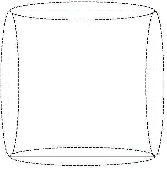
[0080] like Figure 2a to Figure 2c As shown, the present invention provides a micromechanical magnetic field sensor, which at least includes: a resonant oscillator and an insulating layer formed on the surface of the resonant oscillator, a grounded aluminum layer 2 and at least one layer of metal coil; The resonant oscillator includes: a resonant oscillator structure 31 , a main support beam 32 , a first anchor point 33 , a second anchor point 36 , an S-shaped folded beam 34 and a driving electrode 35 ; wherein, the resonant oscillator structure 31 includes four elastic beams. The elastic beam is used as the resonant oscillator structure 31 to reduce the resonant frequency of the entire magnetic sensor, so that the output modulated voltage signal can be easily demodulated by the demodulation chip.

[0081] The resonant oscillator structure 31 is an axisymmetric structure, and the symmetry axis of the resonant oscillator structure 31 includes at least a first symmetry axis and...

Embodiment 2

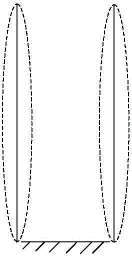
[0118] see Figure 3a and Figure 3b , this embodiment also provides a micro-mechanical magnetic field sensor, the technical solution of this embodiment is basically the same as that of Embodiment 1, the main difference is that the resonant oscillator structure described in Embodiment 1 is four elastic beams and four drive electrodes, and in this embodiment, the resonant oscillator structure is two elastic beams and two driving electrodes; and compared with the first embodiment, a second fixed support structure 38 is added in this embodiment. For the rest of the similarities of the micromachined magnetic field sensor (structure, manufacturing method, working principle and beneficial effects), please refer to the relevant description of the first embodiment, and will not repeat them here.

[0119] The resonant oscillator structure 31 is silicon carbide, and its first axis of symmetry is parallel to the long side or wide side of the first driving electrode. In this example, if...

Embodiment 3

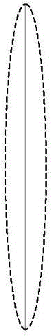
[0125] see Figure 4a and Figure 4b , this embodiment also provides a micro-mechanical magnetic field sensor, the technical solution of this embodiment is basically the same as that of Embodiment 1, the main difference is that the resonant oscillator structure described in Embodiment 1 is four elastic beams and four drive electrodes, and in this embodiment, the resonant oscillator structure is a single elastic beam and a single driving electrode; and compared with the first embodiment, the first fixed support structure 37 is added in this embodiment. For other similarities of the micromachined magnetic field sensor (structure, manufacturing method, working principle and beneficial effects), please refer to the relevant description of Embodiment 1, and details will not be repeated here.

[0126] One end of the first support structure 37 is connected to the S-shaped folded beam 34 close to the first anchor point 33, and the other end is connected to the S-shaped folded beam 36...


PUM


Abstract

The present invention provides a micro-machine magnetic field senor and an application thereof. The sensor at least comprises a resonance oscillator and an insulation layer and at least one layer of metal coil arranged on the surface of the resonance oscillator in order. An S-shaped folding beam is employed to realize the connection of an elastic beam and an anchor to ensure that the resonance oscillator is moved along the direction perpendicular to the resonance oscillator when the resonance oscillator is subjected to resonance and greatly improve the variation of a resonance beam in the enclosed area unit time compared to a square ring formed by a general dual-end fixed support beam so as to increase the variation of the magnetic flux in the metal coil and the sensitivity of a magnetic field. Besides, a grounding aluminium layer is added in the insulation layer of the metal coil to effectively avoid the problem that the signals of the resonance oscillator are coupled to the metal coil. The micro-machine magnetic field senor and the application thereof are simple in structure and reduce the loss of a device with no need for current communication on the metal coil; and moreover, the size of the magnetic field is measured through measurement of the induced electromotive force at two ends of the metal coil, and therefore the influence of the temperature is small.

Description

technical field [0001] The invention belongs to the technical field of micromechanical magnetic field sensor design and detection, and relates to a magnetic field sensor, in particular to a micromechanical magnetic field sensor working in a bending mode and a circuit structure thereof. Background technique [0002] By sensing the earth's magnetic field to identify directions or navigate ships, especially in the fields of navigation, aerospace, automation control, military and consumer electronics, magnetic field sensors are more and more widely used. Magnetic field sensing technology is developing towards the direction of miniaturization, low power consumption, high sensitivity, high resolution and compatibility with electronic equipment. According to the working principle, the magnetic field sensor can be divided into: superconducting quantum interference magnetic field sensor, Hall magnetic field sensor, fluxgate magnetometer, giant magnetoresistive magnetic field sensor a...

Claims


Application Information

Patent Timeline
Patent Type & Authority Applications(China)
IPC IPC(8): G01R33/028B81B3/00
Inventor 熊斌徐华英徐德辉马颖蕾王跃林
Owner SHANGHAI INST OF MICROSYSTEM & INFORMATION TECH CHINESE ACAD OF SCI
Why Eureka
Try Eureka