Device for changing operating force of lens device

Active Publication Date: 2014-09-18
FUJIFILM CORP
View PDF1 Cites 3 Cited by
  • Summary
  • Abstract
  • Description
  • Claims
  • Application Information

AI Technical Summary

Benefits of technology

[0020]The present invention is capable of: applying a load caused by viscosity resistance against rotation of an operating ring so as to obtain an excellent operational feeling; changin

Problems solved by technology

Unfortunately, in a mechanism of adjusting operating torque by changing area of a region, in which a thin plate member is in sliding contact with an inner peripheral surface of an operating ring, by moving a thin plate member arranged on an inner peripheral surface side of the operating ring in the axial direction of a lens barrel, as shown in Japanese Patent Application Laid-Open No. 10-311939, there is a problem of a space allowing the thin plate member to be arranged in a movable manner, that is, a lens barrel is typically downsized to eliminate an excess space as much as possible, therefore, it is difficult to secure a sufficient space for arranging the thin plate member in a movable manner without increasing the size of the lens barrel.
As a result, it is impossible to sufficiently change area of a sliding contact region between the inner peripheral surface of the operating ring and the thin plate member, therefore, there is a problem in which a changing amount (adj

Method used


Image

  • Device for changing operating force of lens device
  • Device for changing operating force of lens device
  • Device for changing operating force of lens device

Examples


Example

[0028]Hereinafter, referring to accompanying drawings, preferable embodiments of the device for changing operating force of a lens device, in accordance with the present invention, will be described in detail.

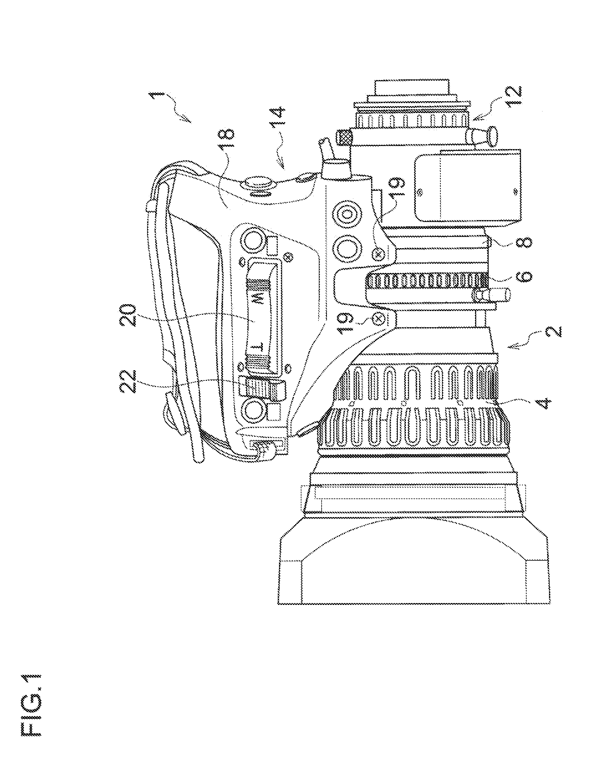
[0029]FIG. 1 is an external view showing an example of a lens device (ENG lens) for a television camera, to which the invention of the present application is applied. An ENG lens 1 shown in FIG. 1 is an inner focus type zoom lens used in a television camera for broadcasting or business use such as an ENG camera, and includes a lens barrel 2 provided with a focus ring 4, a zoom ring 6 and an iris ring 8. The lens barrel 2 is provided its rear end with a mounting part 12 to be detachably mounted on a lens mount of a camera body (camera head) including an imaging element and the like, which is not shown.

[0030]Though detailed description of the internal configuration of the lens barrel 2 is omitted, as is well-known, an imaging optical system supported in the lens barrel 2 includes...


PUM


Abstract

An outer tube body of a device for changing operating force is connected to a gear part of a zoom ring of a lens barrel to rotate the outer tube body together with the zoom ring. The outer tube body has a cylindrical shape and includes a hollow part into which an inner tube body whose rotation is restricted is arranged. Grease is interposed in a gap is formed between an inner peripheral surface of the outer tube body and an outer peripheral surface of the inner tube body. A load caused by viscosity resistance of the grease is applied against rotation of the outer tube body together with the zoom ring. The inner tube body can be displaced in a direction of the center axis so that area of a sliding contact region between the outer tube body and the inner tube body is changed.

Description

CROSS-REFERENCE TO RELATED APPLICATIONS[0001]This application is a continuation application and claims the priority benefit under 35 U.S.C. §120 of PCT Application No. PCT / JP2012 / 078932 filed on Nov. 8, 2012 which application designates the U.S., and also claims the priority benefit under 35 U.S.C. §119 of Japanese Patent Application No. 2011-259331 filed on Nov. 28, 2011, which applications are all hereby incorporated by reference in their entireties.BACKGROUND OF THE INVENTION[0002]1. Field of the Invention[0003]The present invention relates to a device for changing operating force of a lens device, and in particular, to a device for changing operating force of a lens device capable of changing (adjusting) operating force (operating torque) for rotating an operating ring of an imaging lens used in a television camera and the like for broadcasting or business use.[0004]2. Description of the Related Art[0005]In a lens device used in a television camera for broadcasting or business u...

Claims


Application Information

Patent Timeline
IPC IPC(8): G02B7/02
CPCG02B7/026G02B7/102
Inventor TANAKA, MINORUMISAWA, ATSUSHI
Owner FUJIFILM CORP
Why Eureka
Try Eureka