Apparatus and methods for clearing obstructions from surgical cutting instruments

a technology of surgical cutting instruments and obstructions, which is applied in the field of systems, methods and apparatus for clearing obstructions from surgical cutting instruments, can solve the problems of clogging the opening of the cutting edge from tissue, too large in diameter to fit through the opening, and the physician is unable to remove obstructing matter from the instrument, so as to achieve rapid and efficient removal of obstructing matter

Inactive Publication Date: 2007-05-03
SAPPHIRE MEDICAL
View PDF37 Cites 10 Cited by
  • Summary
  • Abstract
  • Description
  • Claims
  • Application Information

AI Technical Summary

Benefits of technology

[0013] In view of the foregoing, it is an object of the present embodiments to provide an apparatus and methods for rapidly and efficiently removing obstructing matter from a surgical cutting instrument.
[0014] It is also an object of the present embodiments to provide apparatus and methods for removing obstructing matter from a surgical cutting instrument without removing it from the surgical site, thereby saving operating time.
[0015] It is a further object of the present embodiments to provide apparatus and methods for removing obstructing matter from a surgical cutting instrument within the surgical site without having to turn off a suction device coupled to the cutting instrument.
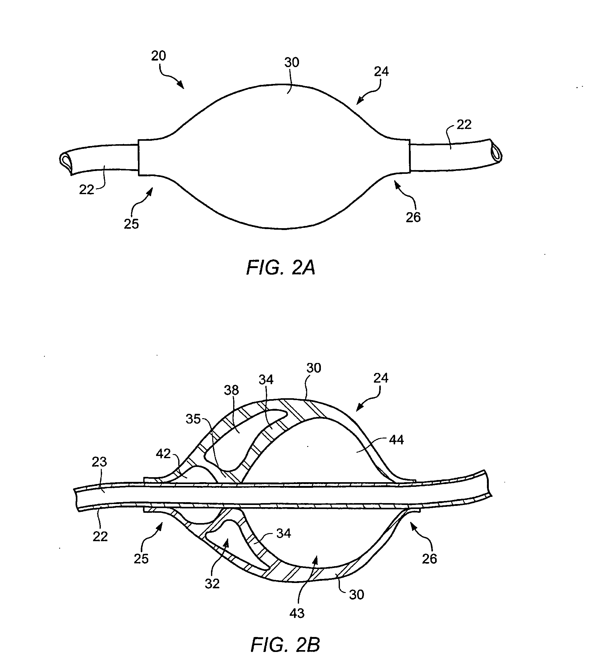
[0019] In an embodiment, a flush lumen may be coupled to the aspiration lumen such that an obstruction may be cleared by delivering a gas through the aspiration lumen. A valve may be included to separate the flush lumen from the aspiration lumen until the valve is opened when a user operates the actuator. The valve may be open for a short time so that the area being treated is not overly inflated. In some embodiments, the valve may be open for less than 0.5 second or less than 0.3 second. The volume of gas passing through the open valve may be less than 500 ml to prevent excessive inflation of the area being treated.
[0021] In an embodiment, a flow element may be used to regulate delivery of the gas from a source of pressurized gas to the gas holding chamber. The flow element may be any suitable element, including a valve, or a fixed flow element. A fixed flow element may be sized to fill the gas holding chamber relatively slowly compared to the rate at which gas leaves the chamber when flushing the aspiration lumen. A flow element may provide direct pressure communication between the gas holding chamber and the source of pressurized gas.

Problems solved by technology

A common problem associated with conventional cutting instruments is clogging of the opening of the cutting edge from tissue that has not been cleanly severed, or is too large in diameter to fit through the opening in the cutting edge.
Many times, the physician is unable to remove obstructing matter from the instrument and must use a new instrument to continue surgery.
Accordingly, clogging of such cutting instruments can cause a significant time delay in arthroscopic surgery and also result in additional costs due to the use of additional cutting instruments.

Method used


Image

  • Apparatus and methods for clearing obstructions from surgical cutting instruments
  • Apparatus and methods for clearing obstructions from surgical cutting instruments
  • Apparatus and methods for clearing obstructions from surgical cutting instruments

Examples


example 1

[0244] A setup using a conventional high pressure (˜2000 psi plus) nitrogen tank and a regulator combined was used to simulate various pressure vessels of 45 psi and

[0245] higher. The output of the regulator was connected to a selected length of elastic polyurethane having calculable and modifiable volume to represent a capacitance element. The regulator acts a flow restrictor (that can be a fixed capillary or filter, or a adjustable regulator) that limits the refill speed of the tubing after it has been opened and depressurized momentarily to release the desired bolus of compressed gas for purging the shaver cannula Using flow restrictor controls the refill and re-pressurization of the tubing acting as a capacitor so as to produce a reservoir that is slow to refill but can be discharged rapidly by a push button momentatry-openable valve having considerably less flow restriction (5× or greater) than the fixed flow restrictor or regulator. The rapidly discharged nitrogen or other ga...


PUM


Abstract

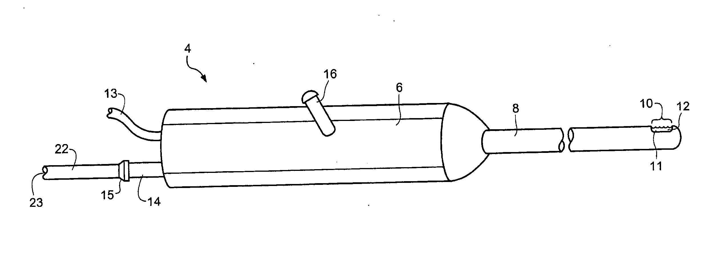
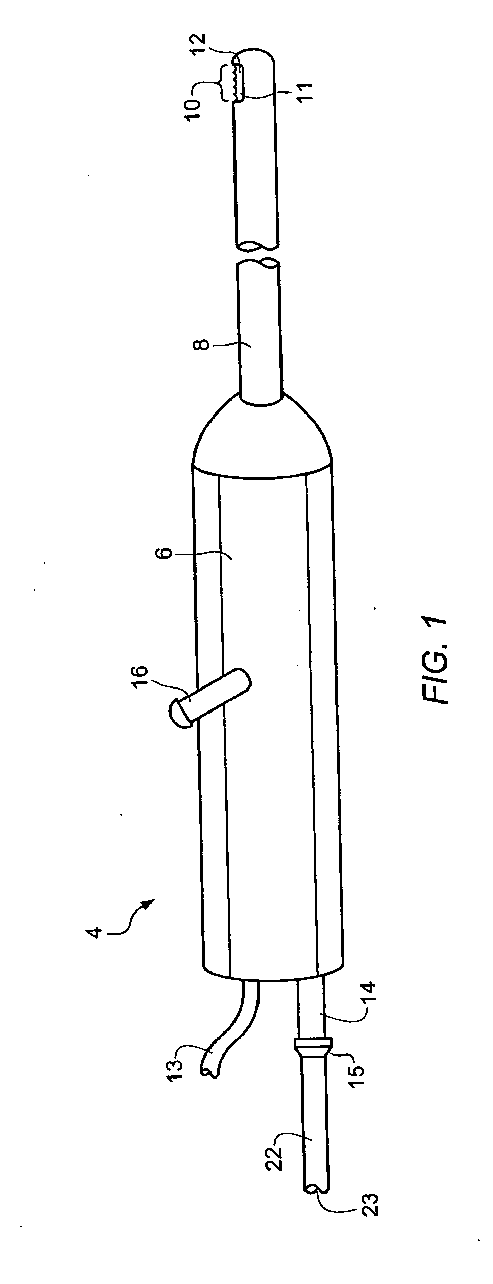
The present invention relates to apparatus and methods for facilitating removal of obstructions from a surgical cutting instrument during a surgical procedure. The apparatus of the present invention is configured to interrupt flow in aspiration tubing when obstructions are detected in the cutting instrument. The apparatus then causes compression of the aspiration tubing to flush fluid towards the cutting instrument, thereby unclogging the instrument in a fast and efficient manner without the need to remove the instrument from the surgical site. A flush lumen is provided to flush a gas through the suction lumen to purge the material obstructing the suction lumen.

Description

REFERENCE TO RELATED APPLICATION [0001] The present application is a continuation of U.S. patent application Ser. No. 11 / 359,885, filed Feb. 21, 2006, which is a continuation-in-part of U.S. patent application Ser. No. 11 / 187,604, filed Jul. 7, 2005, which is a continuation-in-part of U.S. patent application Ser. No. 10 / 782,489, filed Feb. 18, 2004. The above referenced applications are commonly owned with the present application, and the contents thereof are hereby incorporated by reference in their entirety as though fully set forth herein.BACKGROUND [0002] 1. Field of the Invention [0003] The present invention generally relates to systems, methods and apparatus for clearing obstructions from surgical cutting instruments. More particularly, the present invention generally relates to medical devices which use suction to remove detritus from arthroscopic shaving and tissue cutting devices during an arthroscopic procedure without the removal thereof from the incision. [0004] 2. Descr...

Claims


Application Information

Patent Timeline
Patent Type & Authority Applications(United States)
IPC IPC(8): A61B17/20
CPCA61B17/32002A61B2017/0023A61B2017/00367A61B2017/00561A61B2017/32008A61M1/0041A61M1/0058A61M1/0064A61M5/16831A61M39/225A61M2005/1403A61M1/0045A61M1/741A61M1/7415A61M1/774A61M1/83A61M1/76A61M1/77
Inventor FANTON, GARY S.KRUMME, JOHNPEERY, JOHNASHLEY, JOHN E.
Owner SAPPHIRE MEDICAL
Why Eureka
Try Eureka