Blunt tip utility blade

a utility blade and blade technology, applied in the field of utility blades, can solve the problems of user injury, user inadvertent injury, user dislike of rounded cutting corner blades, etc., and achieve the effect of facilitating piercing an obj

Inactive Publication Date: 2007-05-10
BLACK & DECKER INC
View PDF99 Cites 37 Cited by
  • Summary
  • Abstract
  • Description
  • Claims
  • Application Information

AI Technical Summary

Benefits of technology

[0011] In accordance with yet another aspect of the present invention, a utility knife includes a blade body of a generally planar shape, a cutting edge and a pair of opposing side edges. At least one first side edge of the pair of opposing side edges includes a first end and a second end. The first end of the at least one first side edge extends substantially normal to the cutting edge from a terminal end defining the cutting edge. A convex radiused edge extends from the second end of the at least one first side edge. A handle is configured to receive the blade body, wherein the at least one first side edge and at least a portion of said cutting edge are exposed during use. The convex radiused edge provides a substantially blunt profile configured to limit puncture wounds to a user, and the first end of the first side edge provides a sharp profile for facilitating penetration through an object.
[0012] One advantage of the utility blades of the present invention is that at least one corner region of the cutting edge includes a first portion formed at the intersection of the side edge and cutting edge that is substantially perpendicular to the side edge to thereby form a sharp profile that facilitates piercing an object. The corner region also includes a second portion located on an opposite end of the corner region relative to the first portion and defining a convex radiused edge, to thereby provide the corner region with a blunt lateral profile that prevents a user from being inadvertently injured by the corner region as encountered in the above-described prior art utility blades.

Problems solved by technology

Although blades having acute angle cutting corners may be preferred for the reasons described above, the acute angle cutting corner can cause injury to a user.
For example, the blade can cause inadvertent injury when being used, such as by the cutting corner puncturing the skin of the operator.
In practice, some users do not like the rounded cutting corner blades because they do not penetrate the work piece very well.
For example, the rounded point is less efficient as a box cutter.
However, this often violates applicable safety policies.
Thus, although the blade of FIG. 2 reduces the threat of injury to a user, it is less efficient in puncturing a work piece because of the rounded tips.
Each of FIGS. 3 and 4 define the respective cutting edge corners via a side edge having a first end extending from the cutting edge, and a second end intersecting a major side edge and thereby forming an outboard pointed end. FIGS. 3 and 4 represent utility blades having cutting corners that are better suited to penetrate a work piece than the utility blade of FIG. 2, but are not as effective at reducing the risk of puncture wounds to a user because of the exposed pointed end on each outboard side edge of the blade.

Method used


Image

  • Blunt tip utility blade
  • Blunt tip utility blade
  • Blunt tip utility blade

Examples


Embodiment Construction

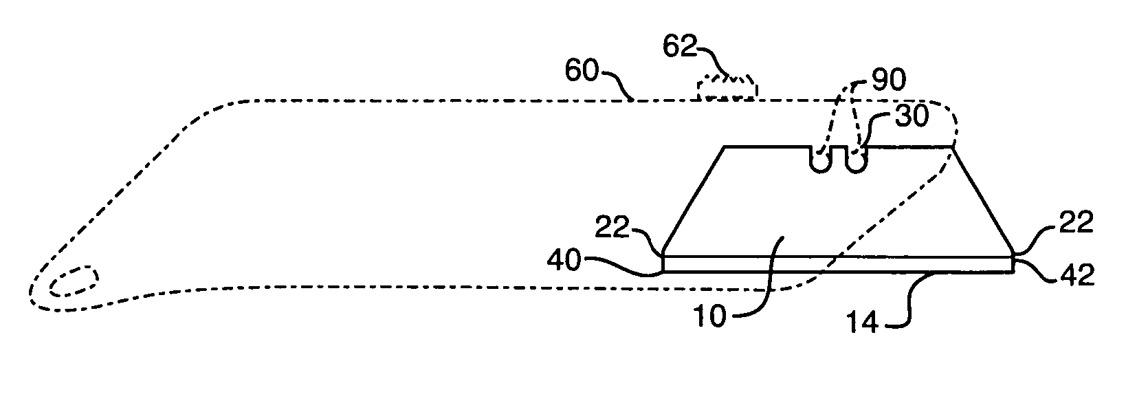
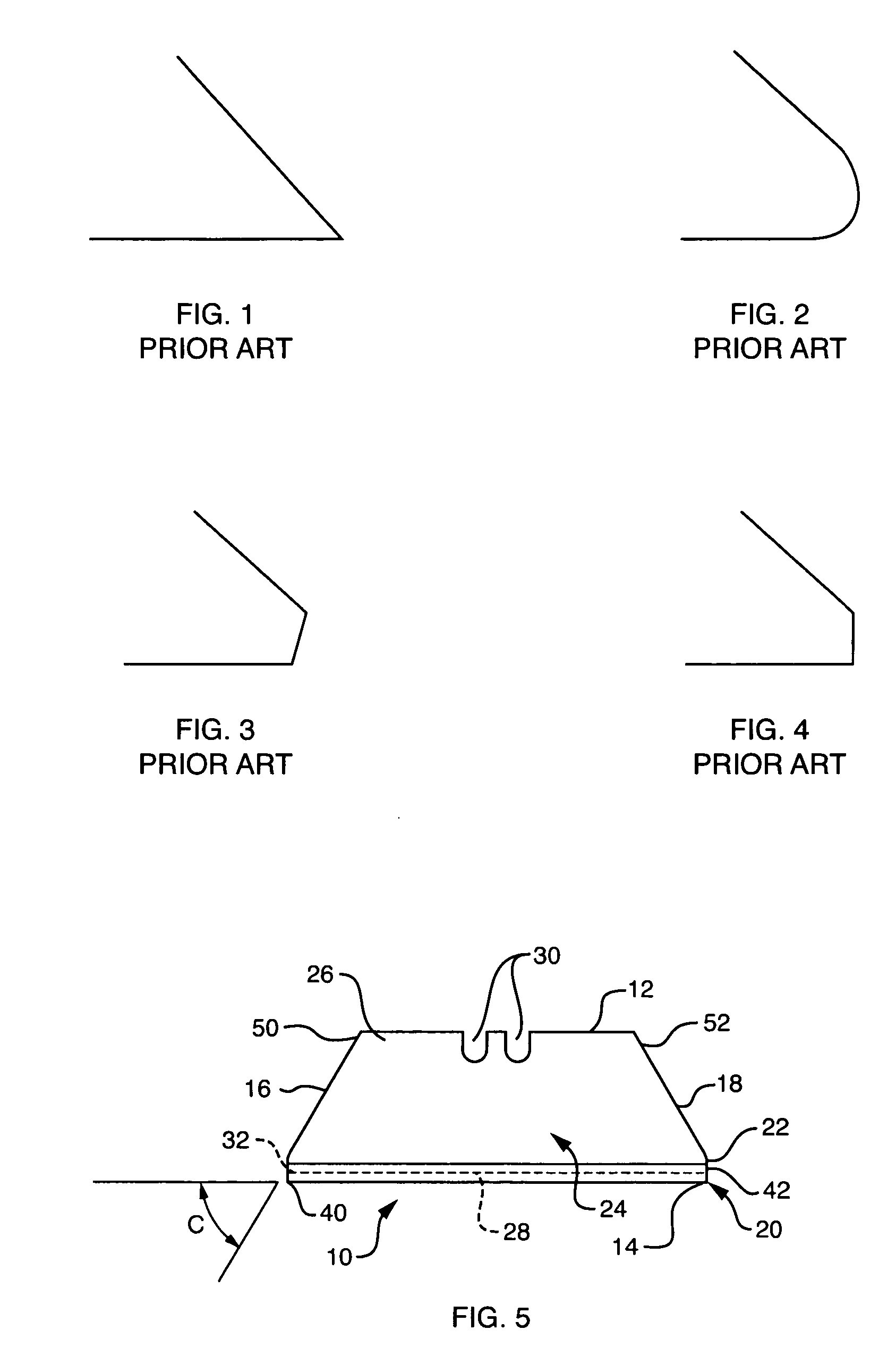
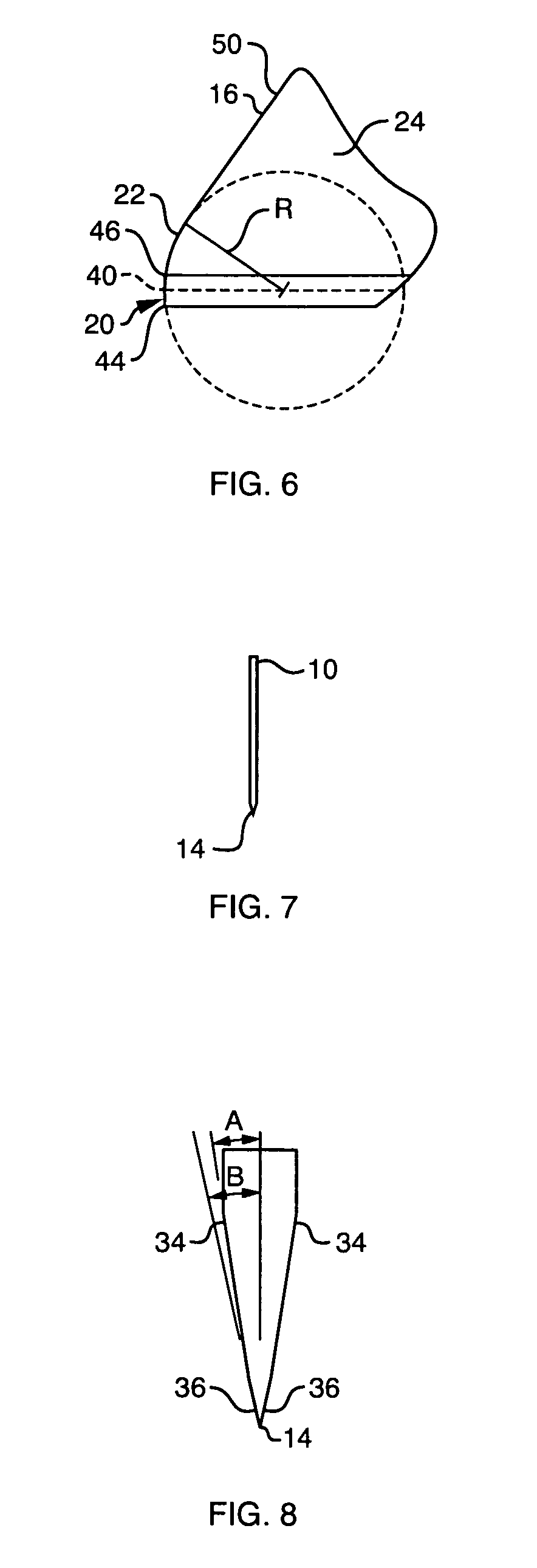
[0025] In FIG. 5, a blunt tip utility knife blade embodying the present invention is indicated generally by the reference numeral 10. The utility knife blade 10 defines a back edge 12, a cutting edge 14 located on an opposite side of the blade relative to the back edge, and two side edges 16, 18 located on opposite sides of the blade relative to each other and extending between the back and cutting edges of the blade. As shown typically in FIG. 5, in the currently preferred embodiment of the present invention, the back, cutting and side edges of the blade preferably define an approximately trapezoidal peripheral configuration. However, as described further below with reference to FIG. 9, for example, the utility knife blade of the present may take any of numerous different shapes or configurations that are currently known or later become known, including, for example, a square or parallelogram shape.

[0026] In the exemplary embodiment of FIG. 5, the blade 10 is a bi-metal blade defi...


PUM


Abstract

A utility blade comprises a blade body having a generally planar shape defined by a cutting edge, an opposite back edge and a pair of opposing side edges. The pair of opposing side edges includes at least one first side edge having a first end and a second end. The first end of the at least one first side edge extends substantially normal to the cutting edge from a terminal end defining the cutting edge. A convex radiused edge extends from the second end of the at least one first side edge. The convex radiused edge provides a substantially blunt profile configured to limit puncture wounds to a user, and the at least one first side edge intersecting with the cutting edge provides a sharp profile for penetration through an object.

Description

CROSS-REFERENCE TO RELATED APPLICATIONS [0001] This application claims priority to U.S. Provisional Application No. 60 / 736,013, filed Nov. 10, 2005, the contents of which are hereby expressly incorporated by reference as part of the present disclosure.BACKGROUND [0002] The present invention relates to utility knife blades, and more particularly, to safety utility knife blades having an exposed side edge which reduces the risk of inadvertent injury to the user while providing suitable penetration through a work piece. [0003] Utility knives having disposable blades are well known in the art. These knives have many industrial as well as home uses, such as for opening boxes, cutting cord, or carving wall board or wood. A typical utility knife has a plastic or metal handle with a retractable blade. When not in use, the blade is retracted into the body of the handle so that the knife can be safely stored or handled. When in use, the blade can extend outwardly from the handle, exposing the...

Claims


Application Information

Patent Timeline
Patent Type & Authority Applications(United States)
IPC IPC(8): B26B21/14
CPCB26B29/02
Inventor GREEN, MATTHEW C.
Owner BLACK & DECKER INC
Why Eureka
Try Eureka