Method of constructing a building, such building, and wall and floor elements for use therein

a building and building technology, applied in the field of building construction methods, can solve the problems of light weight and higher values, and achieve the effect of reducing the number of building components

Inactive Publication Date: 2007-05-10
VEERHUIS BEHEER
View PDF59 Cites 13 Cited by
  • Summary
  • Abstract
  • Description
  • Claims
  • Application Information

AI Technical Summary

Benefits of technology

[0004] An aspect of the present invention is to provide an improved method of constructing a building. The method of constructing a building can include the following steps in a suitable order: providing a skeleton for the building, said skeleton including at least upright building elements, such as columns or dividing walls, placing at least one, lightweight, heat insulating and fire retarding wall element between each adjacent pair of said upright building elements, covering said upright building elements at least on the outside to provide at least a substantially closed outer wall surface, and covering the inner and outer wall surfaces with a covering layer having properties so as to provide at least fire-resistance to the complete wall.
[0008] In this manner, there is provided a method which is simple and which leads to a high quality building with low building costs, but also leads to a building which can conform at least to fire safety regulations without costly additional measures. The building wall can conform to all basic requirements of building regulations, such as compressive strength, wind resistance etc, without costly additional measures.
[0010] After the (outer) building walls of the building have been constructed, the walls may be processed, for example cut, to form openings and recesses in the walls to take up doors, windows, lines and pipes etc. Since the columns and / or dividing walls take up the majority of forces in the building, the openings in the wall elements may be created as desired without deteriorating the structural integrity of the building wall. As the wall elements are hardly loaded, they are not deformed and this obviates the need for frames around windows which are normally intended to protect the glass from forces in the wall. This reduces the building costs further. Frames are only necessary for supporting movable windows. Since there is great freedom in making openings in the walls and since these openings could be made only after constructing the walls of the building, the design of the building may be changed in a late stage of the building process. This makes the building concept very flexible.
[0014] This reinforcement layer provides added strength to the wall elements in order to provide resistance against external forces, such as wind or the like. A reinforcement layer on the inner side of the building may also provide added strength for mounting purposes inside the house, for example for hanging objects to the walls.

Problems solved by technology

Nevertheless, higher values can also be considered lightweight.

Method used


Image

  • Method of constructing a building, such building, and wall and floor elements for use therein
  • Method of constructing a building, such building, and wall and floor elements for use therein
  • Method of constructing a building, such building, and wall and floor elements for use therein

Examples


Embodiment Construction

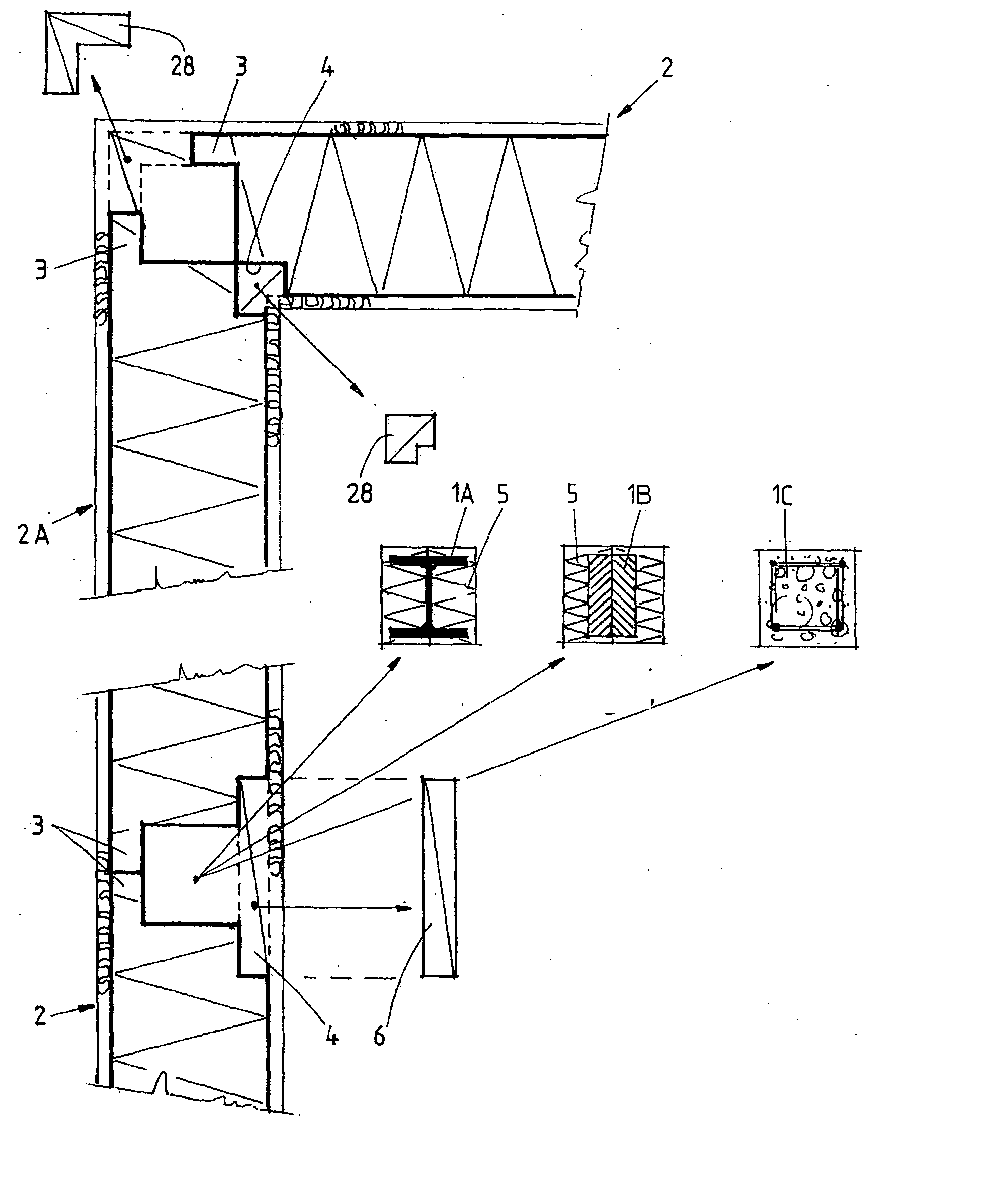
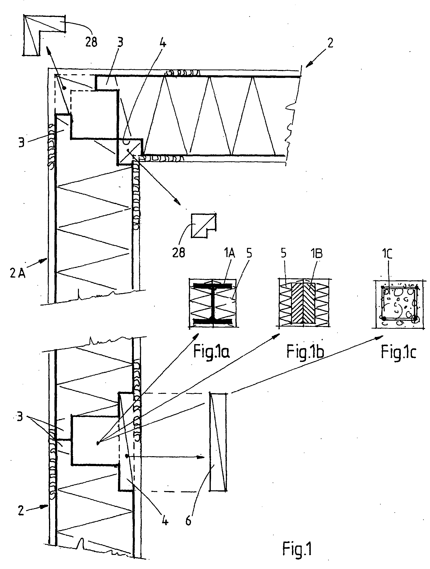
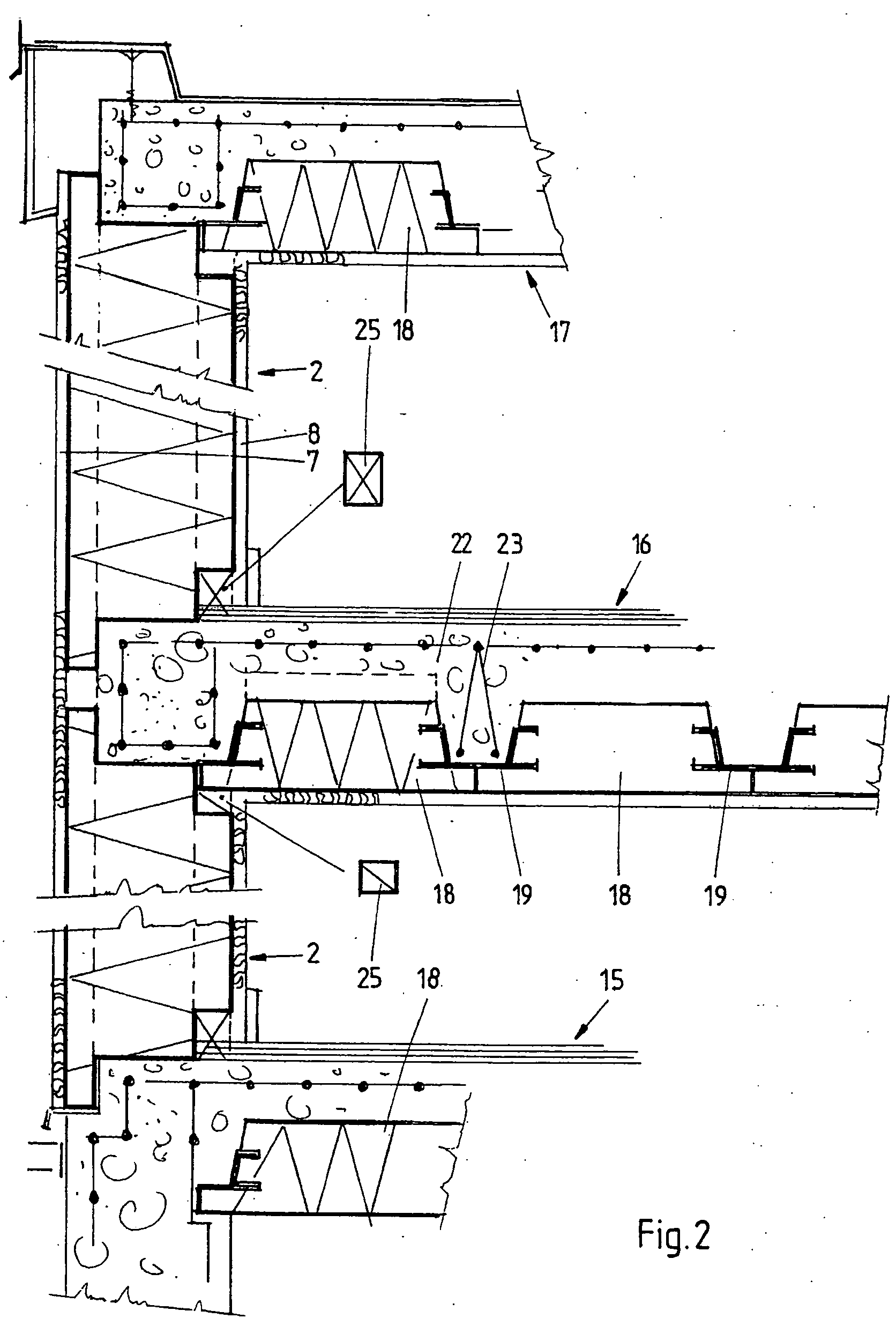
[0033] The drawings, and in first instance FIG. 1-3 show a part of a building wall in accordance with one aspect of the present invention. This building may be a house, but also buildings like offices or other utility buildings are conceivable. FIGS. 1 and 2 show that the building wall comprises a skeleton including upright building elements, in this case columns 1, and wall elements 2 filling the space between the columns 1. As is shown in FIGS. 1a, 1b and 1c the columns may consist of steel (FIG. 1a), wooden (FIG. 1b) or concrete (FIG. 1c) columns 1a, 1b, 1c. The concrete columns may be prefab columns or may be poured in situ. The wall elements 2 can have such dimensions, that they completely fill the space between the columns of one story, so that there is only one wall element 2 between each adjacent pair of columns 1. This obviates the need for complicated (mechanical) connections between wall elements.

[0034]FIGS. 5-7 show the shape of one wall element 2. From FIG. 5 it is cle...


PUM

PropertyMeasurementUnit
widthaaaaaaaaaa
lengthaaaaaaaaaa
thickaaaaaaaaaa

Abstract

The invention relates to a method of constructing a building, comprising the step of providing a skeleton for a building wall of the building. The skeleton includes at least upright building elements such as columns or dividing walls. At least one lightweight, heat insulating and fire retarding wall element is placed between each adjacent pair of said columns. The columns are covered to provide substantially closed wall surfaces. The wall surfaces are covered with a covering layer having properties so as to provide fire-resistance to the complete wall. The covering layer on the inside wall surface may include a base layer of modified resin mortar, and a top layer of plaster mortar. The covering layer on the outside wall surface may include a base layer of modified resin mortar and a top layer of mineral mortar. Lightweight, heat insulating floor elements are placed and interconnected, and supported if necessary, and thereafter structural fill-material, such as concrete, is poured onto the floor elements to form a floor. The invention also includes a building, and wall and floor elements.

Description

CROSS-REFERENCE TO RELATED APPLICATION [0001] The present application is based on and claims the benefit of U.S. provisional patent application Ser. No.______ , filed Oct. 26, 2005, titled METHOD OF CONSTRUCTING A BUILDING, SUCH BUILDING, AND WALL AND FLOOR ELEMENTS FOR USE THEREIN, the content of which is hereby incorporated by reference in its entirety.BACKGROUND OF THE INVENTION [0002] The invention relates to a method of constructing a building, a building preferably constructed according to this method and wall and floor elements for use therein. [0003] In the prior art, several building methods are known in which lightweight wall elements are used. In most cases, the wall elements are made of expanded polystyrene. Examples of these methods and the resulting buildings are disclosed in U.S. Pat. No. 5,353,562, U.S. Pat. No. 4,823,534 and U.S. Pat. No. 5,617,686. SUMMARY OF THE INVENTION [0004] An aspect of the present invention is to provide an improved method of constructing a ...

Claims


Application Information

Patent Timeline
Patent Type & Authority Applications(United States)
IPC IPC(8): E04B1/00
CPCE04B1/164E04B1/20E04B1/24E04B1/26E04B5/19E04B2001/2466E04B2001/2481E04B2001/2484E04C2/205
Inventor VEERMAN, ALBERTUS THEODORUS GERARDUSSIMONS, AIJE JACOBBOS, BERNARDUS JOHANNES
Owner VEERHUIS BEHEER
Why Eureka
Try Eureka