Method and system for error checking an electrochemical sensor

an error checking and electrochemical sensor technology, applied in the field of electrochemical sensors, can solve the problems of changing the detection surface in the measuring chamber, and the geometry of the detection zone in the measuring chamber deviating from the specification of individual test carriers

Active Publication Date: 2007-05-10
ROCHE DIAGNOSTICS OPERATIONS INC
View PDF8 Cites 56 Cited by
  • Summary
  • Abstract
  • Description
  • Claims
  • Application Information

AI Technical Summary

Problems solved by technology

Deviations in the dimensions lead to deviations in the measuring result.
In doing so there is a risk that the geometry of the detection zone in the measuring chamber deviates from the specifications for individual test carriers.
It is, however, also possible that test carriers become deformed due to mechanical or thermal stress after manufacture resulting in a change in the detection surface in the measuring chamber.
Furthermore, it is conceivable that the electrode surface itself was not manufactured in the intended geometric dimensions or was changed by subsequent damage.
A disadvantage of this method is that the actual measurement process is used as a control.
Thus especially in the case of lengthy measurements (e.g., in the field of coagulation diagnostics) it may take a relatively long time until it is known whether a sensor is OK or not.
In the prior art there is a lack of methods which would enable the above-mentioned problems to be reliably detected and thus avoid erroneous measurements or to flag such measurements as erroneous.

Method used


Image

  • Method and system for error checking an electrochemical sensor
  • Method and system for error checking an electrochemical sensor
  • Method and system for error checking an electrochemical sensor

Examples


example 1

Checking Electrochemical Sensors

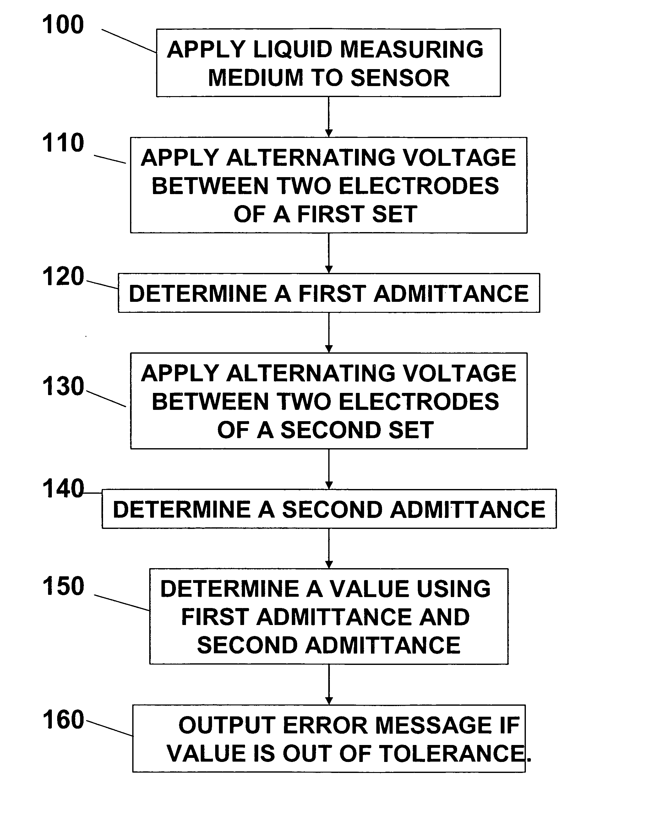
[0072] An alternating voltage (8 mV; 10 kHz) is applied for a period of 0.15 seconds to the electrode Set 1 of sensor 10 and the conductivity is measured. The signal that is determined is referred to as the first admittance (Ad1).

[0073] After a waiting time (1 second), an alternating voltage (8 mV; 10 kHz) is applied to the electrode Set 2 of sensor 10 for a period (3 seconds), and the conductivity is measured. The signal that is determined is referred to as the second admittance (Ad2).

[0074] The quotients of first admittance and second admittance (Ad2 / Ad1) are determined as the so-called “failsafe admittance” signals.

example 2

Detection of Defective Coagulation Test Strips

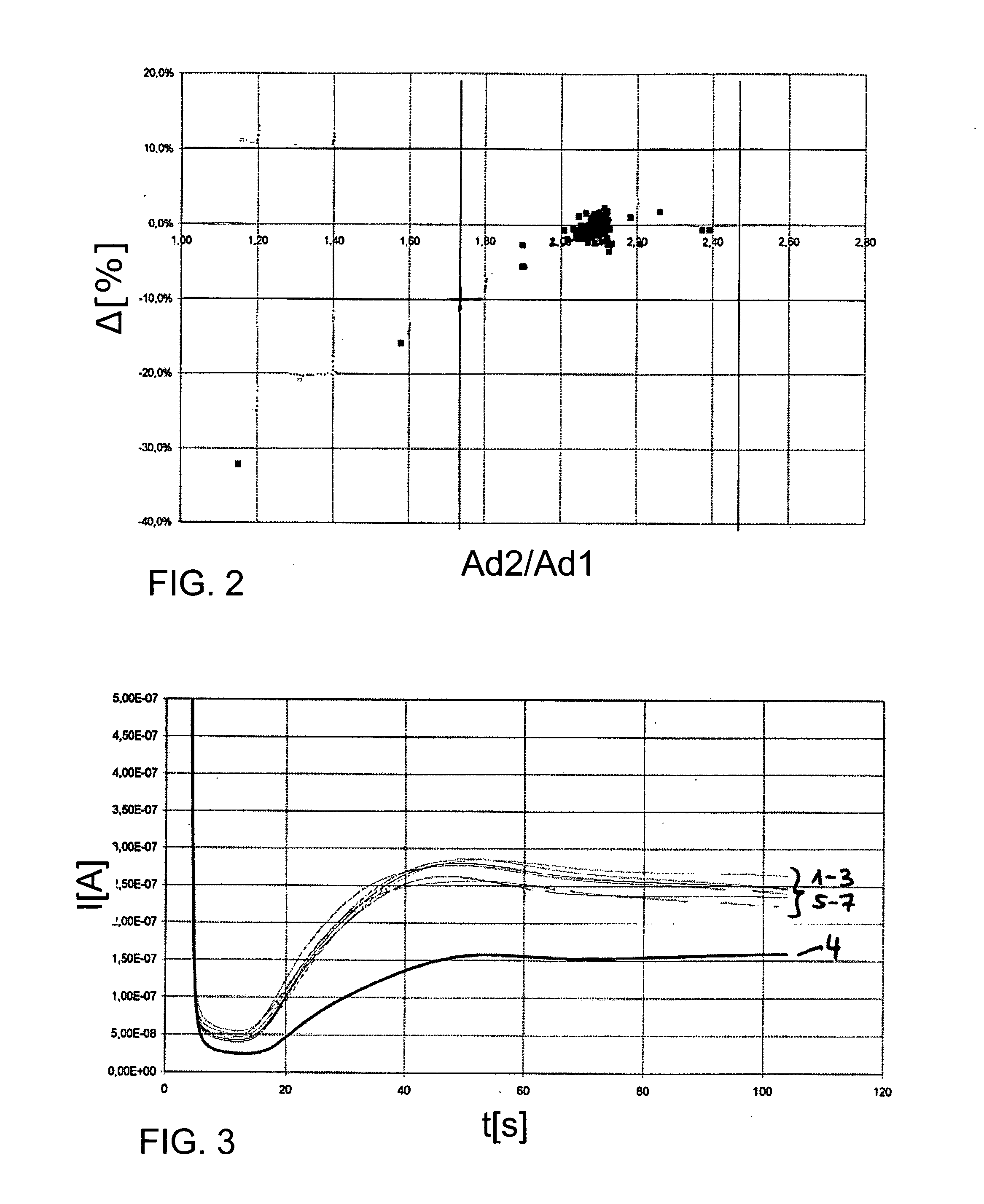
[0075] The parameter “failsafe admittance” (Ad2 / Ad1) for diverse coagulation test strips of Example 1 is plotted against the coagulation time measured with these test strips in FIG. 2.

[0076] A target range was defined for the failsafe admittance (vertical continuous lines). All test strips whose failsafe admittance was within the target range exhibit coagulation values within a very narrow window (+ / −10%; horizontal continuous lines) around the mean value for the batch.

[0077] All test strips for which coagulation times are measured outside of the 10% window are detected as defective because they generate “failsafe admittance” signals which lie outside the “failsafe admittance” target range.

TABLE 1Comparison of the admittance ratios for five exemplary test stripsand the coagulation values that were measured with them.Coagulation time [s]Admittance A [10−4]Assessmentrel.AssessmentStripSampleA1A2A2 / A1admittanceactualtargetdeviationcoag...

example 4

Coagulation Test Strips with an Electrode Surface that is Too Large

[0083]FIG. 4 shows current / time curves that were generated as described in Example 2.

[0084] Three experiments were run using three test strips (see Table 3). Intact test strips were used in experiments 1 and 2. A test strip was used in experiment 3 whose working electrode had an active surface that was too large as is observed for example when sample liquid migrates under a spacer which determines the working electrode geometry. Currents that were too high were measured for this test strip. This results in coagulation times that are too short.

[0085] As shown in Table 3 the test strip whose working electrode had an active surface that was too large was detected as defective by the parameter “failsafe admittance”.

TABLE 3Comparison of the admittance ratios for three exemplary test stripsand the coagulation values that were measured with them.Coagulation time [s]Admittance A [10−4]Assessmentrel.AssessmentStripA1A2A2...


PUM

PropertyMeasurementUnit
thicknessaaaaaaaaaa
frequencyaaaaaaaaaa
alternating voltageaaaaaaaaaa

Abstract

A method and a corresponding system for error checking an electrochemical sensor having at least two electrodes and a liquid measuring medium applied thereto are disclosed. The method comprises determining a first admittance between a first set of electrodes of the sensor; determining a second admittance between a second set of electrodes of the sensor; determining a value using the first admittance and the second admittance; and displaying an error message if the value is out of a predetermined tolerance.

Description

FIELD OF THE INVENTION [0001] The present invention relates generally to electrochemical sensors, and more particularly to a method and a corresponding system for error checking an electrochemical sensor comprising at least two electrodes. BACKGROUND OF THE INVENTION [0002] Diagnostic systems analyzing body fluids such as whole blood, plasma, serum, urine, etc., use test carriers (such as test strips, cassettes etc.) to take up a fluid sample to be examined. Such test carriers usually have a sample application site and a measuring chamber that is spatially separated therefrom. The structure of the test carrier must ensure that the sample is transported from the sample application site to the measuring chamber and that the latter is adequately filled with sample liquid. Capillaries can for example be used for this liquid transport as they are described for example in WO 03 / 095092 or WO 2004 / 113917. [0003] The measuring chamber usually comprises a detection zone which has a defined ge...

Claims


Application Information

Patent Timeline
Patent Type & Authority Applications(United States)
IPC IPC(8): G01N27/26
CPCG01N27/3274
Inventor DREIBHOLZ, JOERGSAECKER, SYLVIAUNKRIG, VOLKER
Owner ROCHE DIAGNOSTICS OPERATIONS INC
Why Eureka
Try Eureka