Blood processing apparatus with controlled cell capture chamber and method background of the invention

a technology of blood processing apparatus and cell capture chamber, which is applied in the direction of centrifuges, separation processes, filtration separation, etc., can solve the problems of reducing the “platelet viability of the platelet, inefficient conventional porous filters, and introducing their own set of problems, so as to achieve a greater taper

Inactive Publication Date: 2007-05-10
CARIDIANBCT
View PDF2 Cites 66 Cited by
  • Summary
  • Abstract
  • Description
  • Claims
  • Application Information

AI Technical Summary

Benefits of technology

[0012] The present invention comprises a centrifuge for separating particles suspended in a fluid, particularly blood and blood components, and methods for controlling the centrifuge. The apparatus has a fluid separation chamber mounted on a rotor, the fluid separation chamber having a fluid inlet and a fluid outlet, the fluid inlet being radially outward from the fluid outlet, a first frustro-conical segment adjacent the fluid inlet and radially inward therefrom, a second frustro-conical segment immediately adjacent the first frustro-conical segment and radially inward therefrom, the second frustro conical segment having a taper such that particles within the second frustro-conical segment are subjected to substantially equal and opposite centrifugal and fluid flow forces. The taper of the second frustro-conical segment is selected based on the expected size of particles and expected flow rates, such that at least particles of the average size of expected particles will be subjected to substantially equal and opposite centripetal and fluid forces. The taper may be at least 2.8°, more preferably about 3.0°, such that particles having a size greater than the average size of expected particles will be subjected to such equal and opposite forces. Preferably, the first frustro-conical segment has a greater taper than the second frustro-conical segment.

Problems solved by technology

However, use of the porous filter introduces its own set of problems.
Conventional porous filters may be inefficient because they may permanently remove or trap approximately 5-20% of the platelets.
These conventional filters may also reduce “platelet viability” meaning that once passed through a filter a percentage of the platelets cease to function properly and may be partially or fully activated.
In addition, porous filters may cause the release of bradykinin, an inflammation mediator and vasodialator, which may lead to hypotensive episodes in a patient.
Porous filters are also expensive and often require additional time-consuming manual labor to perform a filtration process.
Although porous filters are effective in removing a substantial number of white blood cells, activated platelets may clog the filter.
Therefore, the use of at least some porous filters is not feasible in on-line processes.
Thus, some elutriation processes only permit separation in particle batches and require an additional fluid medium to transport particles.

Method used


Image

  • Blood processing apparatus with controlled cell capture chamber and method background of the invention
  • Blood processing apparatus with controlled cell capture chamber and method background of the invention
  • Blood processing apparatus with controlled cell capture chamber and method background of the invention

Examples


Embodiment Construction

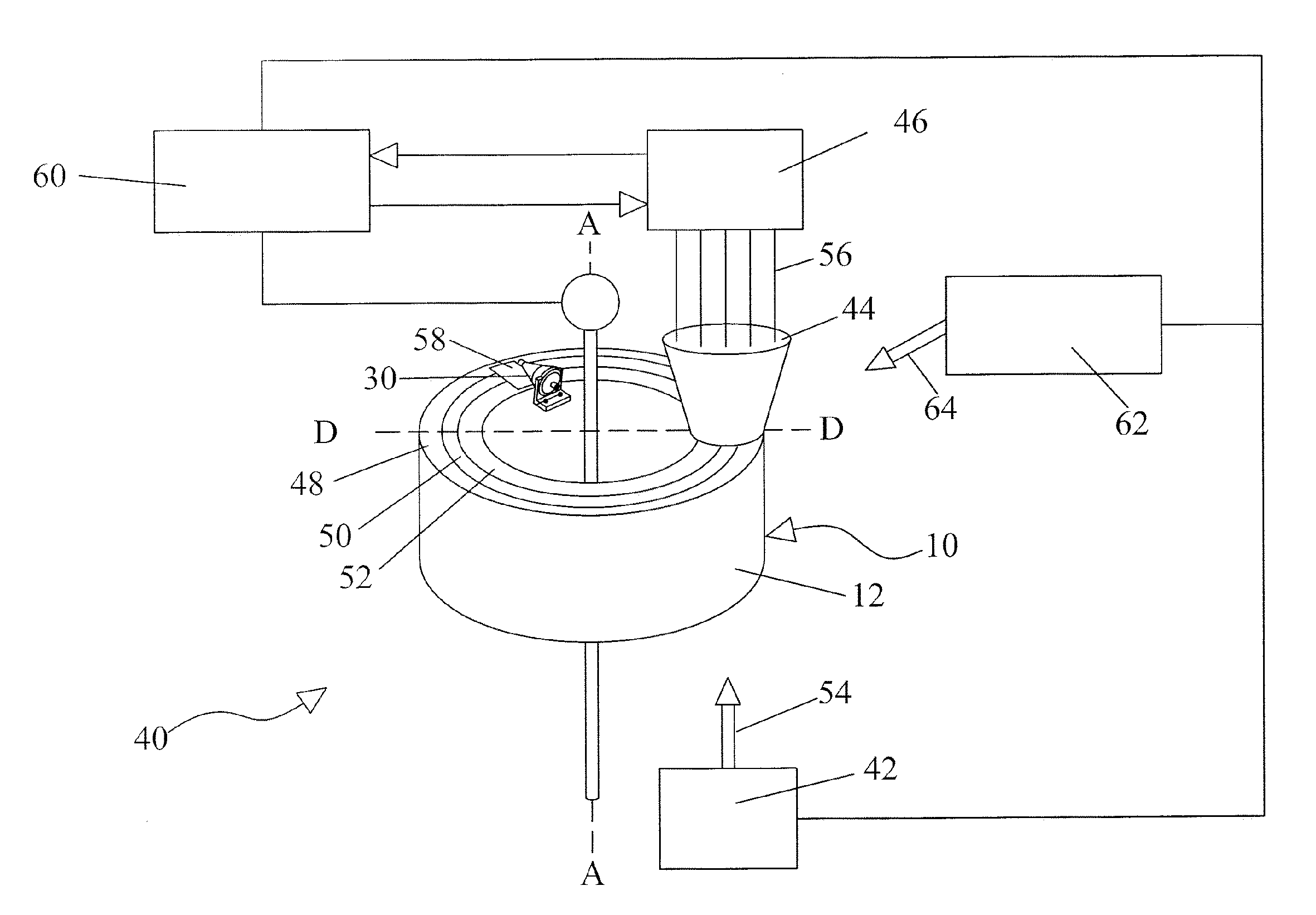
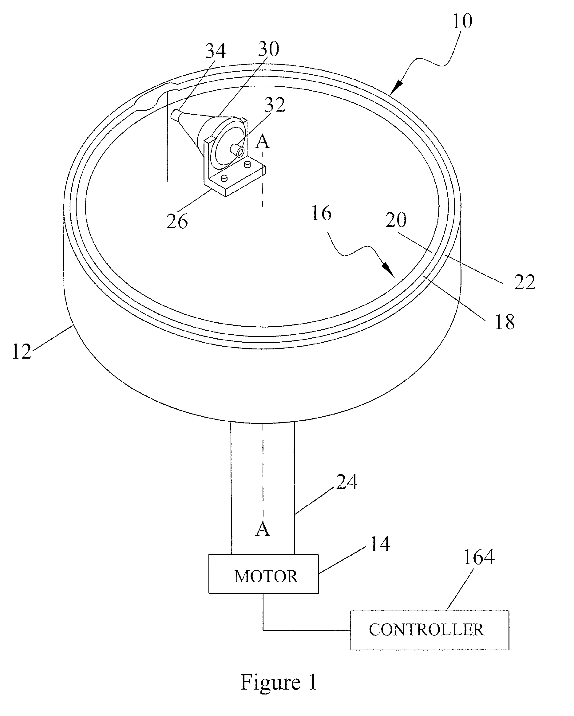
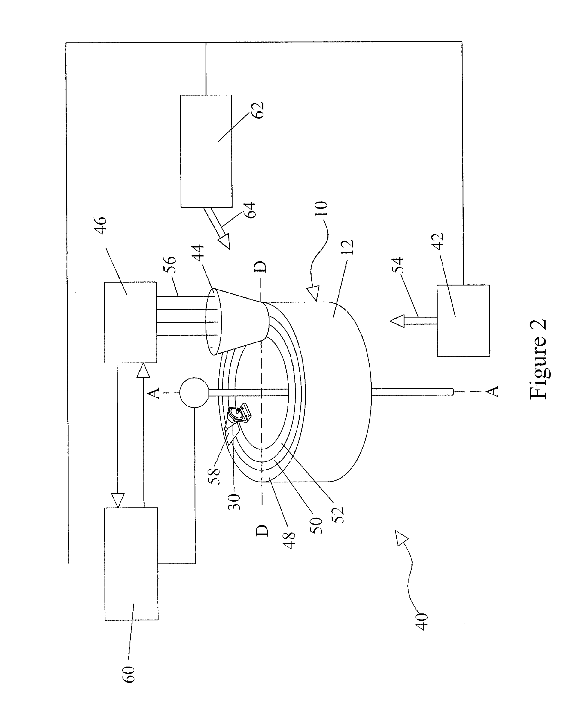
[0028] To describe the present invention, reference will now be made to the accompanying drawings.

[0029] The present invention preferably comprises a blood processing apparatus having a camera control system, as disclosed in U.S. patent applications Ser. Nos. 10 / 884,877 and 10 / 905,353. It may also be practiced with a TRIMA® blood component centrifuge manufactured by Gambro BCT, Inc. of Colorado or, alternatively, with a COBE® SPECTRA™ single-stage blood component centrifuge also manufactured by Gambro BCT, Inc. Both the TRIMA® and the SPECTRA™ centrifuges incorporate a one-omega / two-omega sealless tubing connection as disclosed in U.S. Pat. No. 4,425,112 to Ito, the entire disclosure of which is incorporated herein by reference. The SPECTRA™ centrifuge also uses a single-stage blood component separation channel substantially as disclosed in U.S. Pat. No. 4,094,461 to Kellogg et al. and U.S. Pat. No. 4,647,279 to Mulzet et al., the entire disclosures of which are also incorporated h...


PUM

PropertyMeasurementUnit
wavelengthsaaaaaaaaaa
thicknessaaaaaaaaaa
angleaaaaaaaaaa

Abstract

A centrifuge for separating blood components, and methods for controlling the centrifuge. The apparatus has a fluid separation chamber having a first frustro-conical segment and a second frustro-conical segment. The second segment has a taper such that particles are subjected to substantially equal and opposite centripetal and fluid flow forces. A camera observes fluid flow, and a controller controls the flow. White blood cells are selectively captured within the second segment and are periodically flushed out of the fluid separation chamber. The camera is used to determine the quantity of particles captured. A limited quantity of high density particles, such as red blood cells, may be captured within the first segment before capturing relatively low density particles, such as white blood cells, within the second segment.

Description

[0001] This application is related to U.S. Pat. No. 5,722,926, issued Mar. 3, 1998; U.S. Pat. No. 5,951,877, issued Sep. 14, 1999; U.S. patent 6,053,856, issued Apr. 25, 2000; U.S. patent 6,334,842, issued Jan. 1, 2002; U.S. patent application Ser. No. 10 / 884,877 filed Jul. 1, 2004; and U.S. patent application Ser. No. 10 / 905,353, filed Dec. 29, 2004. The entire disclosure of each of these U.S. patents and patent applications is incorporated herein by reference.FIELD OF THE INVENTION [0002] The present invention relates to an apparatus and method for separating particles or components of a fluid. The invention has particular advantages in connection with separating blood components, such as white blood cells and platelets. DESCRIPTION OF THE RELATED ART [0003] In many different fields, liquids carrying particle substances must be filtered or processed to obtain either a purified liquid or purified particle end product. In its broadest sense, a filter is any device capable of removin...

Claims


Application Information

Patent Timeline
Patent Type & Authority Applications(United States)
IPC IPC(8): C02F1/38
CPCA61M1/3693B04B5/0442B04B2005/0471A61M1/3696A61M1/3692
Inventor KOLENBRANDER, JEREMY
Owner CARIDIANBCT
Why Eureka
Try Eureka