
Specimen enclosure apparatus and containers and closure devices for the same

a technology for specimen enclosures and containers, applied in the field of specimen enclosure apparatuses and containers, can solve the problems of difficult sterilization of this interface, standard lyophilization stoppers, and dry heat generally not as effective at killing microorganisms

Inactive Publication Date: 2007-05-10
BIOMERIEUX INC
View PDF15 Cites 40 Cited by
  • Summary
  • Abstract
  • Description
  • Claims
  • Application Information

AI Technical Summary

Benefits of technology

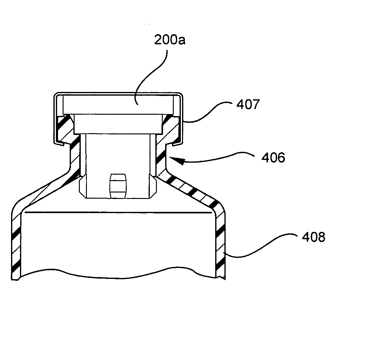
[0009] Embodiments of the present invention include a specimen enclosure apparatus. The specimen enclosure apparatus includes a container having a cavity configured to receive the specimen and an opening extending through a neck of the container to the cavity. An internal flange is positioned intermediate the neck of the container. The specimen enclosure apparatus further includes a closure device configured to be received in the opening. The closure device has a flange seal portion configured to contact the internal flange to form a flange seal proximate the cavity and further has a radial travel limiter integrally formed with the closure device that is configured to contact the container in the opening to limit radial movement of the flange seal portion relative to the internal flange.

Problems solved by technology

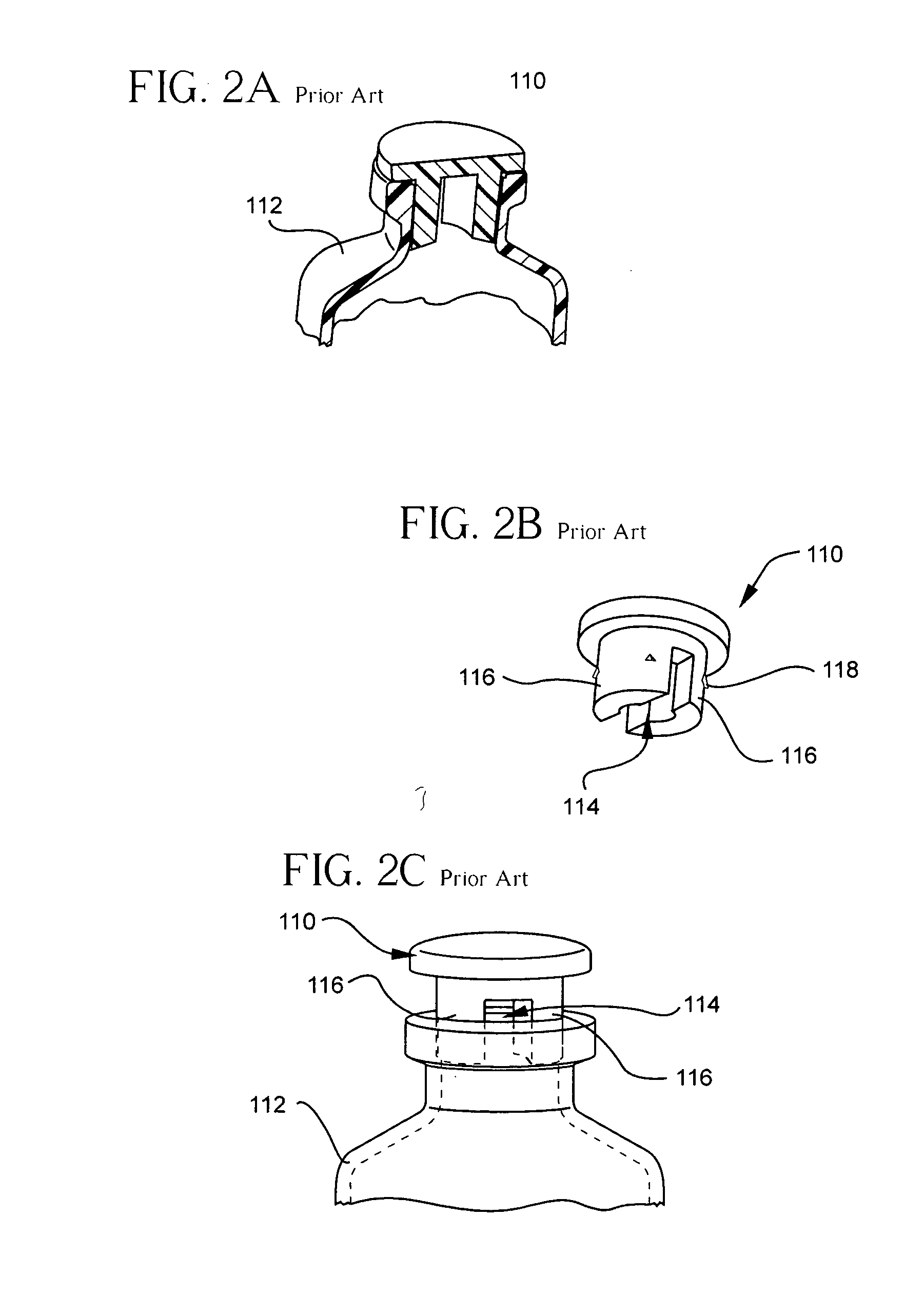
The limitations of a standard lyophilization stopper depend on the applications of the product.
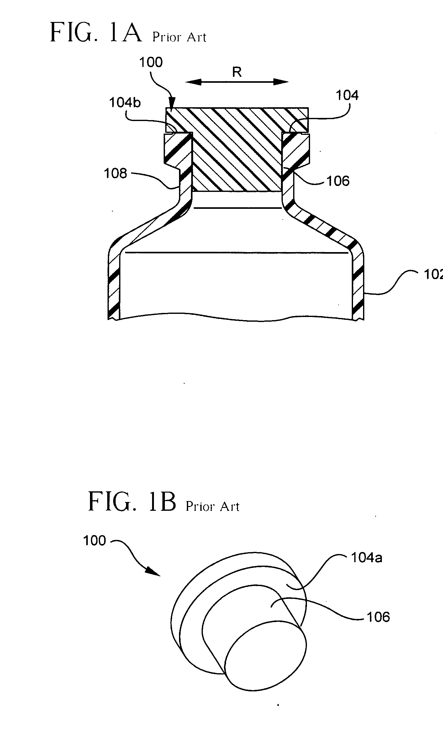
For aseptic product applications, which generally use autoclave terminal sterilization, the movement of the surface contact (interface) between the stopper and bottle or vial can make it difficult to sterilize this interface.
However, dry heat is generally not as effective at killing microorganisms as moist heat.
This radial movement may break the integrity of the flange seal between the septum and vial.

Method used


Image

  • Specimen enclosure apparatus and containers and closure devices for the same
  • Specimen enclosure apparatus and containers and closure devices for the same
  • Specimen enclosure apparatus and containers and closure devices for the same

Examples


Embodiment Construction

[0044] The present invention now will be described more fully hereinafter with reference to the accompanying drawings, in which illustrative embodiments of the invention are shown. In the drawings, the relative sizes of regions or features may be exaggerated for clarity. This invention may, however, be embodied in many different forms and should not be construed as limited to the embodiments set forth herein; rather, these embodiments are provided so that this disclosure will be thorough and complete, and will fully convey the scope of the invention to those skilled in the art.

[0045] It will be understood that, although the terms first, second, etc. may be used herein to describe various elements, components, regions, layers and / or sections, these elements, components, regions, layers and / or sections should not be limited by these terms. These terms are only used to distinguish one element, component, region, layer or section from another region, layer or section. Thus, a first ele...


PUM


Abstract

Embodiments of the present invention include a specimen enclosure apparatus. The specimen enclosure apparatus includes a container having a cavity configured to receive the specimen and an opening extending through a neck of the container to the cavity. An internal flange is positioned intermediate the neck of the container. The specimen enclosure apparatus further includes a closure device configured to be received in the opening. The closure device has a flange seal portion configured to contact the internal flange to form a flange seal proximate the cavity and further has a radial travel limiter integrally formed with the closure device that is configured to contact the container in the opening to limit radial movement of the flange seal portion relative to the internal flange. Containers and closure devices are also provided.

Description

RELATED APPLICATION [0001] The present application claims the benefit of and priority from U.S. Provisional Application No. 60 / 718,655, (Attorney Docket No. 01072), filed Sep. 20, 2005, the disclosure of which is hereby incorporated herein in its entirety by reference.BACKGROUND OF THE INVENTION [0002] The present invention relates to apparatus for enclosing a specimen, reagants and components thereof. In particular, the present invention relates to an apparatus for enclosing a specimen that can be used in a microbial detection and / or characterization system. [0003] Various apparatus for enclosing specimens are known in the art. Typically, such apparatus include a specimen container or bottle and a closure or stopper for the specimen container or bottle. Further, several types of closures are known for use with specimen containers or bottles. A standard closure, for example, for medical vials is a rubber stopper. A rubber stopper can seal a vial or bottle by either a plug seal or a ...

Claims


Application Information

Patent Timeline
IPC IPC(8): B65D51/00B65D39/00
CPCB01L3/50825B01L2300/042B01L2300/048B01L2300/049B65D39/0005B65D41/16B65D45/322B65D51/241
Inventor COLIN, BRUNOBAEYAERT, SYLVAINRONSICK, CHRISWILSON, MARKROBINSON, RON
Owner BIOMERIEUX INC
Learn More