Rotisserie oven and hood

a rotisserie oven and hood technology, applied in the field of rotisserie ovens, can solve the problems of inability to visually inspect food without opening, flavorful gasses may escape, and the conventional rotisserie oven suffers from several drawbacks,

Inactive Publication Date: 2007-05-10
SWANK PHILIP D +5
View PDF44 Cites 45 Cited by
  • Summary
  • Abstract
  • Description
  • Claims
  • Application Information

AI Technical Summary

Benefits of technology

[0013] In accordance with one aspect of the invention, a rotisserie oven is provided for preparing cooked food product from a raw food product. The oven includes a cooking chamber defined by side walls joined at their outer ends to upper and lower walls. The cooking chamber defines at least one open end that is closed by a movable door assembly. A radiating heating system is disposed in the cooking chamber that receives electricity and produces radiating heat. A convection heat system is also disposed in the cooking chamber, and includes A) one

Problems solved by technology

Unfortunately, conventional rotisserie ovens suffer from several drawbacks.
For instance, if the door to the cooking chamber is not sufficiently sealed, flavorful gasses may escape from the oven.
Furthermore, conventional ovens allow condensation to accumulate on the interior surface of the glass door, thereby inhibiting a user's ability to visually inspect the food without opening the door.
Additionally, conventional spit assemblies are difficult to disassemble for cleaning purposes.
Moreover, conventional ovens do not provide a user-friendly method for removing grease produced during cooking, and additionally fail to provide a user-friendly method and apparatus for cleaning th

Method used


Image

  • Rotisserie oven and hood
  • Rotisserie oven and hood
  • Rotisserie oven and hood

Examples


Embodiment Construction

[0051] I.

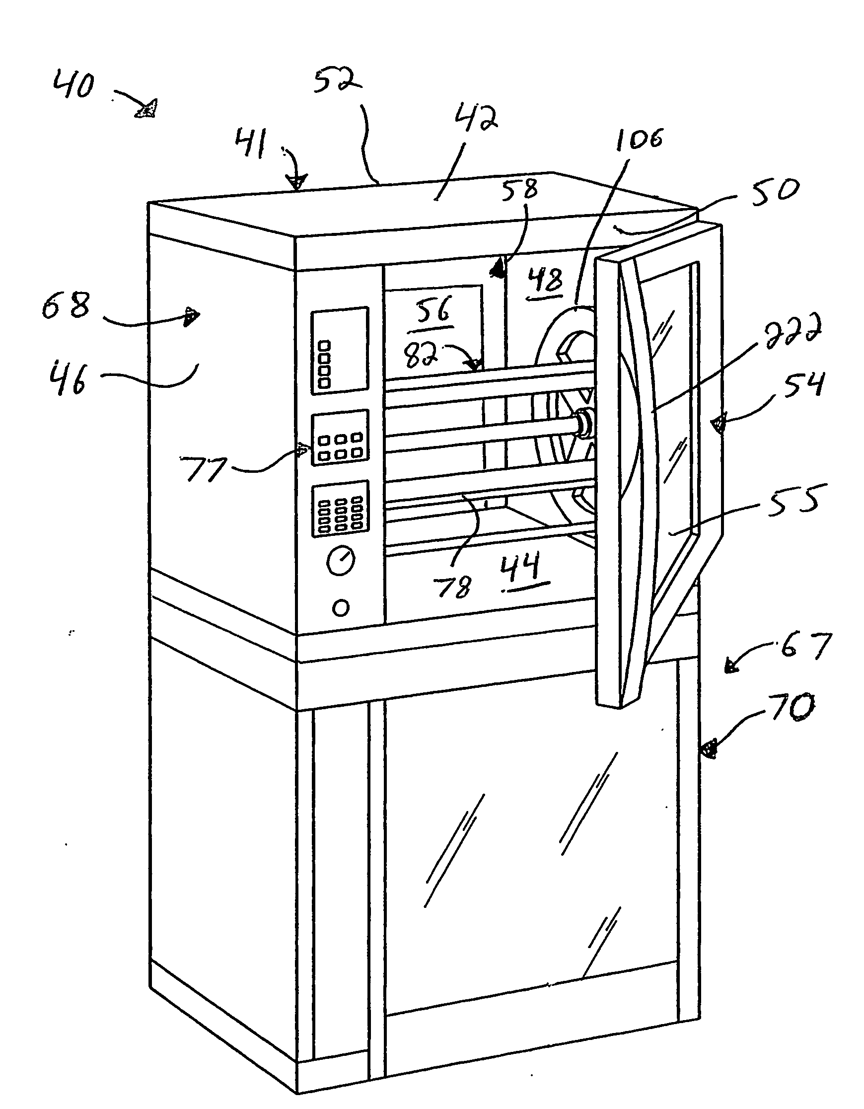
[0052] Referring initially to FIG. 1, a rotisserie oven 40 includes an outer housing 41 having upper and lower walls 42 and 44, respectively, opposing left and right side walls 46 and 48, respectively, and opposing front and rear walls 50 and 52 (shown in FIG. 2), respectively. A cooking chamber 58 is defined by upper and lower walls 42 and 44, right side wall 48, and a left side wall 64 (See FIG. 14).

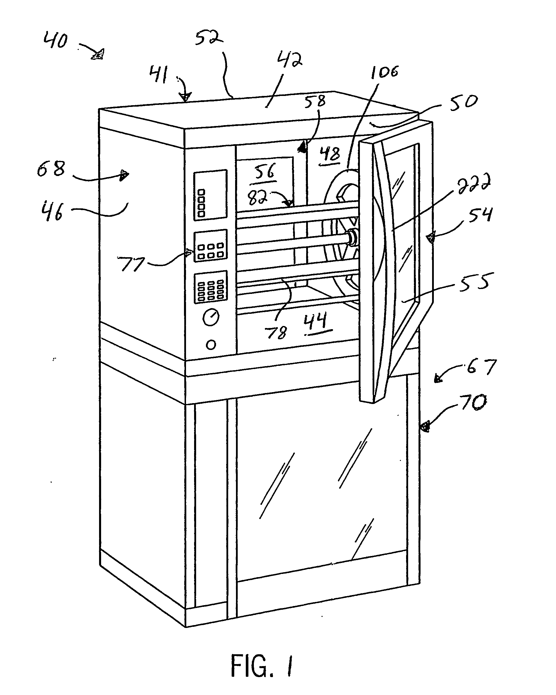
[0053] Wall 64 is spaced from wall 46 that together define the lateral boundaries of a cabinet 68 that contains control components (e.g., a microprocessor, not shown, or other suitable controller) of oven 40. In particular, cabinet 68 houses a control assembly (not shown) that controls various aspects of the oven 40, such as temperature control, cooking sequences, and cleaning functions as is described in more detail below. Cabinet 68 further houses a motor 74 (See FIG. 2) that drives a spit assembly 82. Oven operation is controlled by an operator via a set of user controls ...


PUM


Abstract

A rotisserie oven is provided having a radiating heating system in combination with a convection heating system to prepare raw meat and poultry food product inside of a cooking chamber. A spit assembly carries the food product, and includes components that are detachable to assist in cleaning. The oven further includes a steam cleaning assembly that is integrated with the convection heating system that assists in grease removal from the components inside the cooking chamber. A humidity removal system regulates the moisture level inside of the cooking chamber during food preparation. A rotisserie oven is provided of the type that includes a cooking chamber having at least one open end closed by a movable door assembly. A radiating heating system is disposed in the cooking chamber and receives electricity to produce radiating heat to cook food carried by a rotating spit assembly. A hood assembly is supported by the cooking chamber, and defines a filtration chamber that receives incoming grease-laden air from the cooking chamber and houses at least one filtration member drawing the incoming air therethrough towards a hood outlet. The hood assembly and cooking chamber move together as the rotisserie oven travels from one location to another.

Description

CROSS-REFERENCE TO RELATED APPLICATIONS [0001] This is a continuation-in-part of U.S. patent application Ser. No. 10 / 428,796 filed May 2, 2003, which is a continuation-in-part of U.S. patent application Ser. No. 10 / 078,845, filed Feb. 19, 2002, now issued as U.S. Pat. No. 6,608,288, the disclosures of each of which are hereby incorporated by reference as if set forth in their entirety herein. This further claims priority to U.S. Provisional Patent Application 60 / 467,518, filed May 2, 2003, the disclosure of which is hereby incorporated by reference as if set forth in its entirety herein.BACKGROUND OF THE INVENTION [0002] I. [0003] The present invention relates generally to cooking apparatuses, and in particular to rotisserie ovens. [0004] Rotisserie ovens are traditionally used to cook raw meat and poultry product, such as chicken, duck, and the like in side a cooking chamber. In particular, the food product to be prepared is carried by a rotating spit assembly that brings the food ...

Claims


Application Information

Patent Timeline
IPC IPC(8): F27D11/00A21B3/02A47J27/62A47J39/00F24C15/02
CPCA21B3/02A47J27/62A47J37/042F24C15/02F24C15/164F24C15/327
Inventor SWANK, PHILIP D.INSISIENGMAY, PHILIP C.FARCHIONE, DAVIDLEMCKE, MICHAELREHM, ERICH B.HANSEN, WILLIAM J.
Owner SWANK PHILIP D
Why Eureka
Try Eureka