Ice protection system for aircraft

a technology for aircraft wings and ice protection, which is applied in the direction of automatic actuation, transportation and packaging, and spars/stringers, etc. it can solve the problems of reducing the lift force generated by the wing, increasing drag, and severe ice formation on the wings of aircra

Active Publication Date: 2007-05-10
AMERICAN HONDA MOTOR COMPANY
View PDF27 Cites 27 Cited by
  • Summary
  • Abstract
  • Description
  • Claims
  • Application Information

AI Technical Summary

Problems solved by technology

The formation of ice on aircraft wings can be a severe problem.
The presence of ice changes the geometry of the wing, reduces the lift forces generated by the wing and increases drag.
Additionally, ice increases the weight of the wing, thus, compromising the wing's structural integrity.
An anti-ice system does not allow solid ice to even form on the wing, thus, only condensate water is formed on the wing and the water is also blown off by the passing air.
Anti-ice systems usually consume large amounts of aircraft power.
This system consumes considerable electric power.
This bleed air anti-ice system does not require electrical power, but extracting bleed air from the engine causes power loss affecting the engine thrust.
In either case, a significant amount of power is required for anti-ice systems as compared to de-ice systems.
However, this combination system design still utilizes a great deal of energy.

Method used


Image

  • Ice protection system for aircraft
  • Ice protection system for aircraft
  • Ice protection system for aircraft

Examples


Embodiment Construction

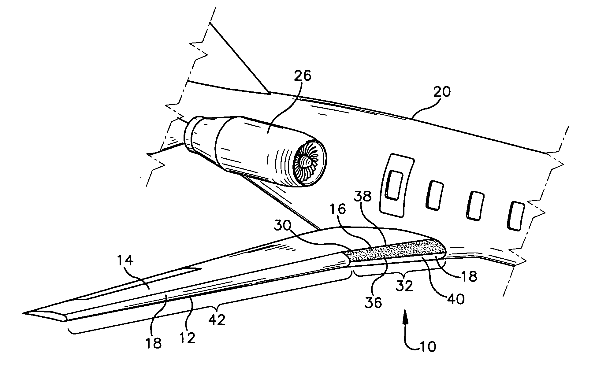
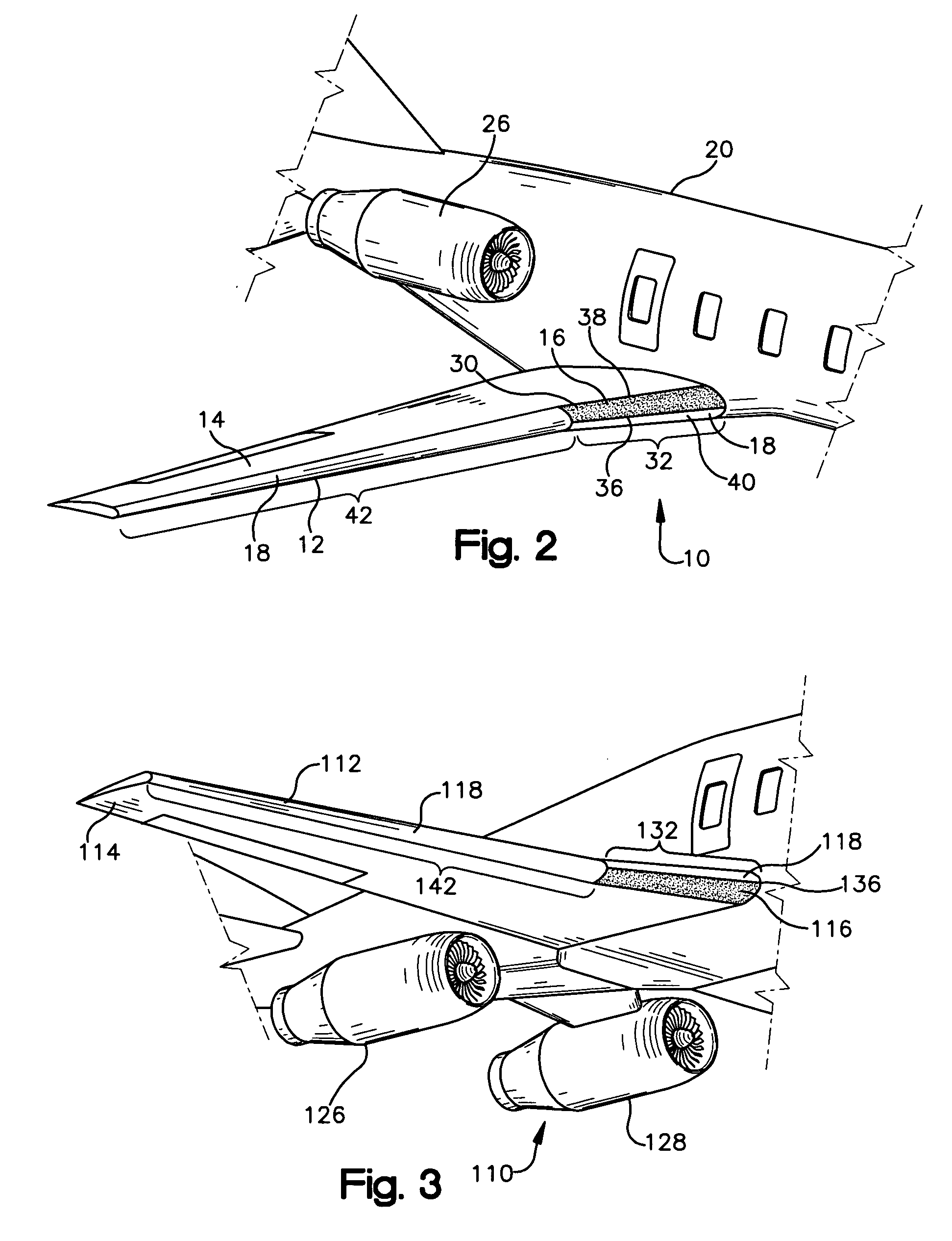
[0015] Referring to the drawings, specifically FIGS. 2 and 4, a preferred ice protection system 10 according to the present invention is illustrated. The ice protection system 10 is employed on the leading edge 12 of an aircraft wing 14 and includes an anti-ice subsystem 16 and a de-ice subsystem 18 configured in a manner to minimize energy consumption while preventing the hazard of ice chunks contacting the aircraft's engines.

[0016] As used within the specification and claims, the term “leading edge” refers to the forward portion of an aircraft wing upon which ice typically forms absent the presence of an anti-ice or de-ice system and such formation is critically detrimental to the aerodynamic function of the wing.

[0017] Referring to FIG. 4, the aircraft of the present invention includes a fuselage 20 that defines a longitudinal center axis “C” and first and second transverse wings 14 and 24 that extend outwardly from the fuselage 20. The aircraft also includes first and second e...


PUM


Abstract

The ice prevention system of the present invention utilizes, in combination, a de-ice subsystem and anti-ice subsystem in a new configuration on an aircraft with engines located behind its wings. Depending on the vertical location of the engines with respect to the wings, the anti-ice subsystem is configured on an upper or lower portion of a leading edge of the wings. If the engine is located above the wing, the anti-ice system is configured only on a section of the wing aligned with the engine and only on the upper portion of the leading edge. If the engine is located below the wing, the placement of anti-ice system is reversed. The de-ice subsystem is configured on the opposite portion of the leading edge adjacent to the anti-ice subsystem and on the remainder of the leading edge of the wing.

Description

BACKGROUND OF THE INVENTION [0001] The formation of ice on aircraft wings can be a severe problem. Ice tends to form from condensation on the leading edge of the wing. The presence of ice changes the geometry of the wing, reduces the lift forces generated by the wing and increases drag. Additionally, ice increases the weight of the wing, thus, compromising the wing's structural integrity. [0002] Two types of ice protection systems, a de-ice system and anti-ice system, are used to reduce the accumulation of ice on aircraft wings. A de-ice system allows solid ice to form on the wing, but removes the ice before it accumulates to a dangerous shape or amount. The accumulating ice is peeled from the wing by the de-ice system and is blown off the wing by passing air. An anti-ice system does not allow solid ice to even form on the wing, thus, only condensate water is formed on the wing and the water is also blown off by the passing air. [0003] Anti-ice systems usually consume large amounts ...

Claims


Application Information

Patent Timeline
Patent Type & Authority Applications(United States)
IPC IPC(8): B64C13/16
CPCB64D15/00B64D27/18
Inventor GOTO, KENICHI
Owner AMERICAN HONDA MOTOR COMPANY
Why Eureka
Try Eureka