Image display device, electronic apparatus, and pixel location determining method

a technology of image display device and location determination method, which is applied in the direction of instruments, computing, electric digital data processing, etc., can solve the problem of not thoroughly considering the influence of the location of sub-pixels on visual characteristics, and achieve the effect of reducing the luminance errors of display images and reducing the edge blurring phenomenon recognized under observation

Inactive Publication Date: 2007-05-10
138 EAST LCD ADVANCEMENTS LTD
View PDF11 Cites 26 Cited by
  • Summary
  • Abstract
  • Description
  • Claims
  • Application Information

AI Technical Summary

Benefits of technology

[0027] According to a further aspect of the invention, there is provided a pixel location determining method for determining locations of four sub-pixels corresponding to different colors in an image display device that displays an image by using a plurality of display pixels, each display pixel including the four sub-pixels. The pixel location determining method includes determining locations of two sub-pixels having a smaller level of luminance so that the two sub-pixels are located at edges of the display pixel, each of the two sub-pixels being located at either edge of the display pixel, and determining the locations of the two other sub-pixels at a central portion of the display pixel such that the absolute value of the difference between a luminance added value, which is a value obtained by adding luminance levels of one of the sub-pixels located at the edges of the display pixel and an adjacent pixel, and a luminance added value, which is a value obtained by adding luminance levels of the other sub-pixel located at the edge of the display pixel and an adjacent pixel, is reduced.
[0028] By applying the locations of the sub-pixels determined in the pixel location determining method to the image display device, luminance errors in display images can be reduced, and the edge blurring phenomenon recognized under observation can be reduced.

Problems solved by technology

In the above-described related art, however, the locations of the RGBC sub-pixels have been determined without thoroughly considering the influence of the locations of sub-pixels on the visual characteristics.

Method used


Image

  • Image display device, electronic apparatus, and pixel location determining method
  • Image display device, electronic apparatus, and pixel location determining method
  • Image display device, electronic apparatus, and pixel location determining method

Examples


first embodiment

[0080] A first embodiment of the invention is described below.

Overall Configuration

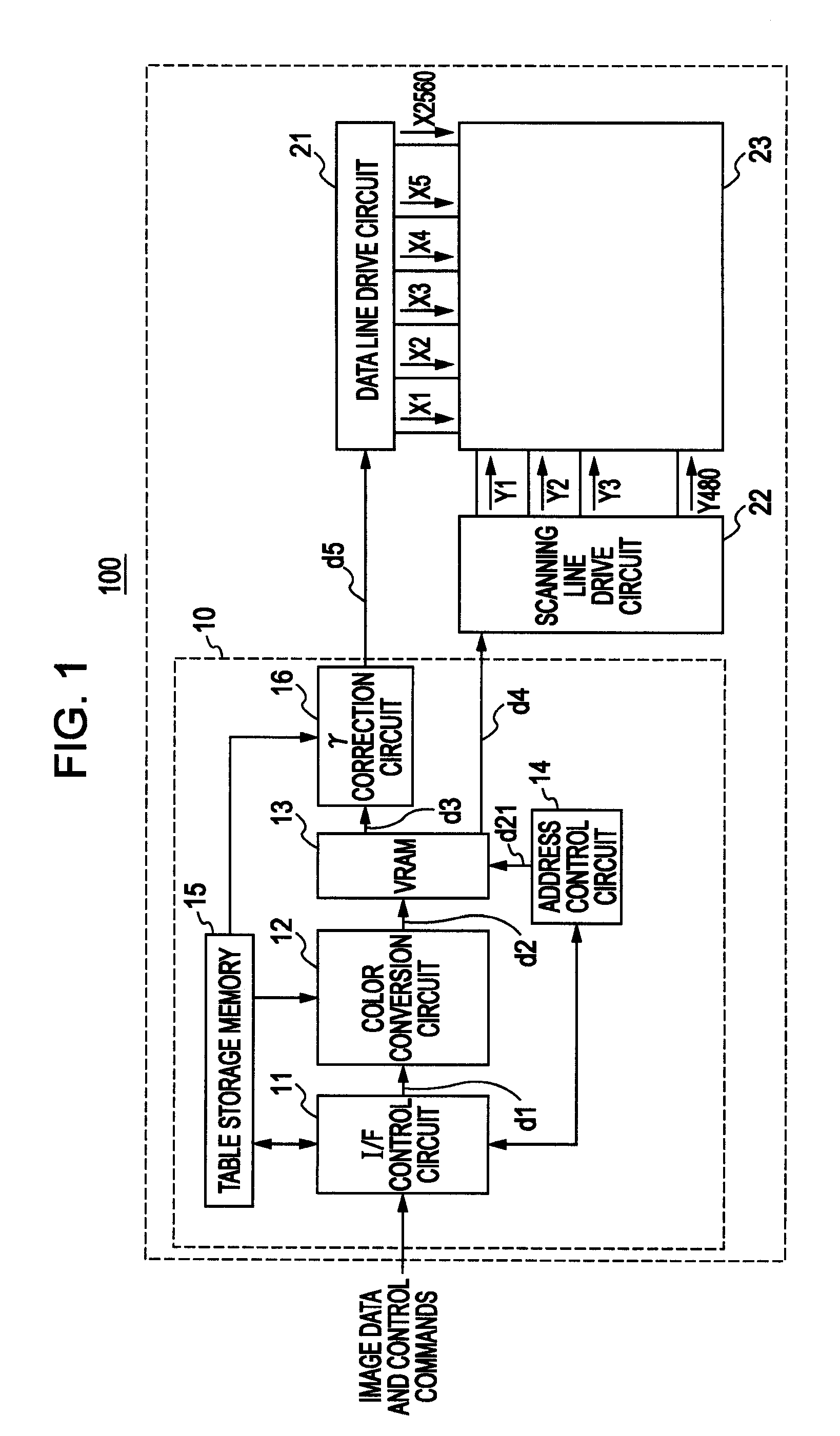
[0081]FIG. 1 is a block diagram illustrating the schematic configuration of an image display device 100 according to the first embodiment of the invention. The image display device 100 includes an image processor 10, a data line drive circuit 21, a scanning line drive circuit 22, and a display unit 23. The image display device 100 can display images by using multiple colors, and more specifically, the image display device 100 can display four colors, such as RGBC colors.

[0082] The image processor 10 includes an interface (I / F) control circuit 11, a color conversion circuit 12, a video random access memory (VRAM) 13, an address control circuit 14, a table storage memory 15, and a gamma (γ) correction circuit 16. The I / F control circuit 11 obtains image data and control commands from an external source (for example, a camera) and supplies image data d1 to the color conversion circuit 12. Image data ...

second embodiment

[0114] A second embodiment of the invention is described below. In the second embodiment, the composition of the multiple colors is different from that of the first embodiment. More specifically, in the second embodiment, instead of cyan (C), white (hereinafter simply referred to as “W” or “Wh”) is used. That is, colors are represented by RGBW. In the second embodiment, an image display device similar to the image display device 100 is used, and an explanation thereof is thus omitted. Additionally, instead of a color layer, a transparent resin layer is used for the W sub-pixels.

[0115]FIGS. 12A through 12D illustrate examples of display characteristics of the display unit 23. More specifically, FIG. 12A is a diagram illustrating the spectral characteristics of the color filter 23c of the display unit 23 in which the horizontal axis represents the wavelength (nm) and the vertical axis indicates the transmission factor (%). The color filter 23c is not used for the W sub-pixels. FIG. 1...

third embodiment

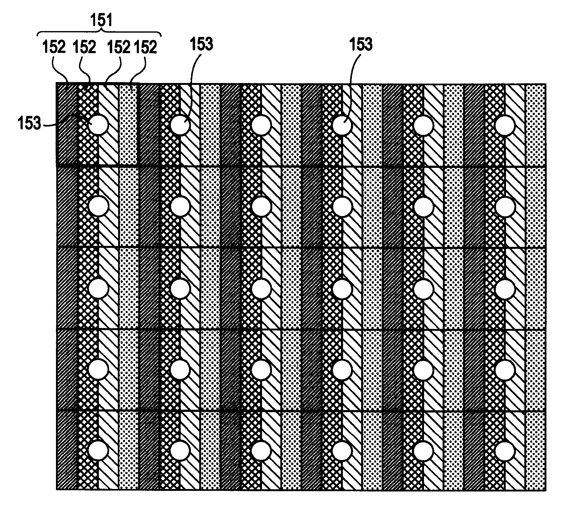
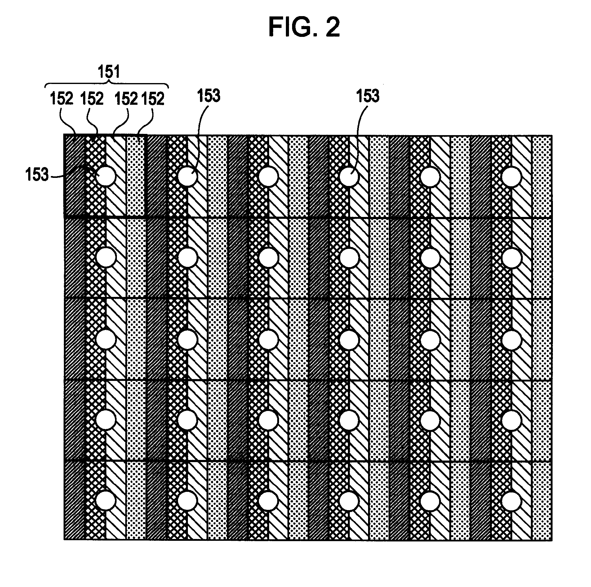
[0128] A third embodiment of the invention is described below. In the first and second embodiments, the display pixels of the display unit 23 are disposed in a stripe pattern. In the third embodiment, however, the display pixels of the display unit 23 are disposed in a manner different from that of the first or second embodiment. Such a pixel arrangement is also referred to as the “display pixel arrangement”.

[0129]FIG. 17 is a block diagram illustrating the schematic configuration of an image display device 101 of the third embodiment. The image display device 101 is different from the image display device 100 (see FIG. 1) of the first embodiment in that a re-sampling circuit 11a for input signals is added and the number of outputs of the data line drive circuit 21 is different from that of the image display device 100. Accordingly, elements and signals similar to those of the image display device 100 are designated with like reference numerals, and an explanation thereof is thus o...


PUM


Abstract

An image display device displays an image by using a plurality of display pixels, each display pixel including four sub-pixels corresponding to different colors. The four sub-pixels forming each of the display pixels are located such that two sub-pixels having a smaller level of luminance are located at edges of the display pixel, each of the two sub-pixels being located at either edge of the display pixel, and such that two other sub-pixels are located at a central portion of the display pixel so that an absolute value of a difference between a luminance added value, which is a value obtained by adding luminance levels of one of the sub-pixels located at the edges of the display pixel and an adjacent pixel, and a luminance added value, which is a value obtained by adding luminance levels of the other sub-pixel located at the edge of the display pixel and an adjacent pixel, is reduced.

Description

CROSS-REFERENCE TO RELATED APPLICATION [0001] This application claims priority from Japanese Patent Application Nos. 2005-298803, 2005-303431, 2006-047875 and 2006-060144, filed in the Japanese Patent Office on Oct. 13, 2005, Oct. 18, 2005, Feb. 24, 2006 and Mar. 6, 2006, respectively, the entire disclosures of which are hereby incorporated by reference in their entireties. BACKGROUND [0002] 1. Technical Field [0003] The present invention relates to image display devices, electronic apparatuses, and pixel location determining methods. [0004] 2. Related Art [0005] Image display devices that can display images by using four or more colors (hereinafter also referred to as “multiple colors”) are known. In this case, the “colors” are colors that can be displayed by sub-pixels, which are the smallest addressable unit for displaying images, and are not restricted to three colors, such as red, green, and blue. The image display devices can display various colors by using various combination...

Claims


Application Information

Patent Timeline
Patent Type & Authority Applications(United States)
IPC IPC(8): G09G5/02
CPCG02F1/133514G02F2201/52G09G3/3607G09G5/02G09G2300/0452G09G2340/0421G09G2340/06G09G3/20
Inventor MORIYA, HIDEKUNIARAGAKI, TAKUMI
Owner 138 EAST LCD ADVANCEMENTS LTD
Why Eureka
Try Eureka