
Power source apparatus

a power source and circuit technology, applied in the direction of electric variable regulation, process and machine control, instruments, etc., can solve the problem of increasing the cost of the power source apparatus

Active Publication Date: 2007-05-10
FUJITSU GENERAL LTD
View PDF4 Cites 51 Cited by
  • Summary
  • Abstract
  • Description
  • Claims
  • Application Information

AI Technical Summary

Benefits of technology

[0004] The present applicant has disclosed a conventional power source apparatus having a boost chopper-type power factor improvement and a harmonic current suppression function. In the conventional power source apparatus, to improve a power factor, when converting an input power to a DC voltage and obtaining a load voltage with a boost chopper circuit, a switching element of the boost chopper circuit is switched to flow short-circuit current via a reactor (boost choke coil). A controller that controls the power source apparatus turns ON or OFF the switching element based on a comparison result between a detected input current by an input current detector and a sinusoidal wave-like input current reference signal. The controller that controls the power source apparatus also switches, for every a half cycle of an AC power source, the switching element a predetermined number of times based on the detection of a zero cross by a power-source phase detection circuit. Thereafter, the switching of the switching element is prohibited to prevent the number of switchings for every half cycle of,the AC power source from fluctuating.

Problems solved by technology

Moreover, a current region of about 12 to 15 Arms also requires a high reactor inductance in order to satisfy the power source harmonic standard, thus increasing the cost of the power source apparatus.

Method used


Image

  • Power source apparatus
  • Power source apparatus
  • Power source apparatus

Examples


Embodiment Construction

[0034] Exemplary embodiments of the present invention will be described in detail with reference to the drawings. It is noted that the embodiments do not limit this invention and all combinations of features described in the embodiments are not required for means for solving the problem of the invention. Components in the following embodiments include those that can be easily assumed by those skilled in the art and those having substantially the same structure. In the following embodiments, a case will be described where the 5-th harmonic component is reduced. However, the present invention is not limited to this and also can be applied to reduce a harmonic component having another order.

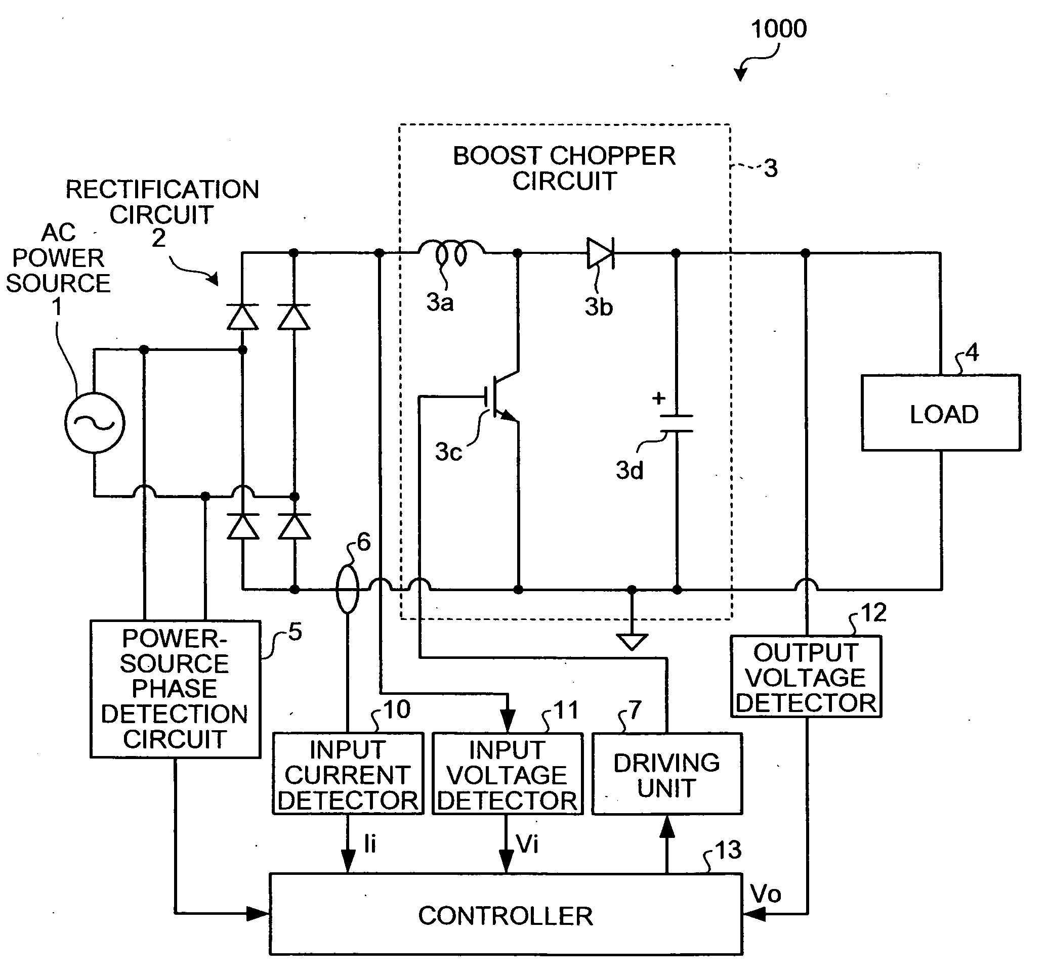
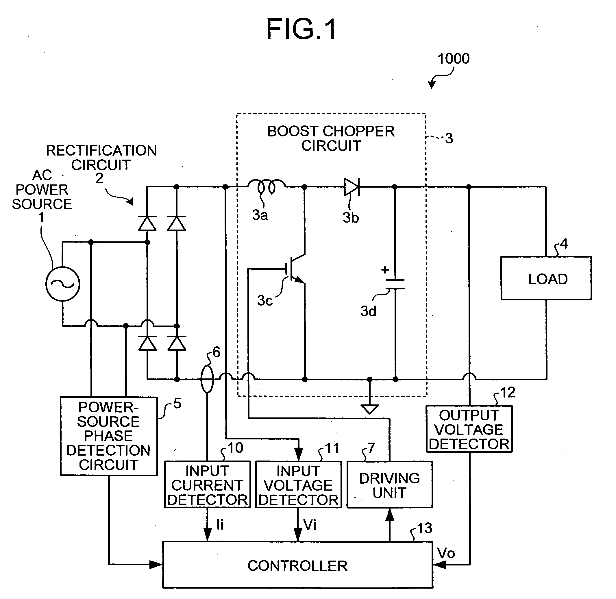
[0035]FIG. 1 is a schematic block diagram of a power source apparatus 1000 according to an embodiment of the present invention. According to the power source apparatus 1000, as in the conventional power source apparatus disclosed in Japanese Patent Application Laid-Open No. 2005-253284, an AC power...


PUM


Abstract

A boost chopper circuit converts AC power to DC voltage and supplies the DC voltage to a load. The boost chopper circuit includes a switching element and a reactor. A controller ON / OFF controls the switching element based on a comparison result in an interval of the former half of a half cycle of the AC power between a detected input current by a input current detector and a current instruction value of a modeling waveform obtained by reducing a harmonic component of a predetermined order from the current waveform.

Description

BACKGROUND OF THE INVENTION [0001] 1. Field of the Invention [0002] The present invention relates to a control technique of a power source circuit that converts a commercial power source to a power source such as a home appliance machine. [0003] 2. Description of the Related Art [0004] The present applicant has disclosed a conventional power source apparatus having a boost chopper-type power factor improvement and a harmonic current suppression function. In the conventional power source apparatus, to improve a power factor, when converting an input power to a DC voltage and obtaining a load voltage with a boost chopper circuit, a switching element of the boost chopper circuit is switched to flow short-circuit current via a reactor (boost choke coil). A controller that controls the power source apparatus turns ON or OFF the switching element based on a comparison result between a detected input current by an input current detector and a sinusoidal wave-like input current reference si...

Claims


Application Information

Patent Timeline
IPC IPC(8): H02M1/14
CPCH02M1/12H02M1/4225Y02B70/126Y02B70/10
Inventor TAGUCHI, YASUTAKAICHIKI, SATOSHIKINPARA, HIROYUKI
Owner FUJITSU GENERAL LTD
Learn More