Temperature sensor

Active Publication Date: 2007-05-10
DENSO CORP
View PDF6 Cites 26 Cited by
  • Summary
  • Abstract
  • Description
  • Claims
  • Application Information

AI Technical Summary

Benefits of technology

[0022] Still further, according to another aspect of the present invention, it is acceptable that the notch part has a flat surface. This shape of the notch part can be easily worked in manufacturing.
[0023] Still f

Problems solved by technology

In particular, when the temperature sensor is placed near the internal combustion engine of the vehicle, severe or large vibration is applied to the temperature sensor, and the vibration increases a possibility of forcedly contacting the temperature sensor with the cover, and severe shock is thereby applied to the thermistor element.
However, this technique of the conventional p

Method used


Image

  • Temperature sensor
  • Temperature sensor
  • Temperature sensor

Examples


Example

First Embodiment

[0052] A description will be given of the temperature sensor according to the first embodiment of the present invention with reference to FIG. 1 to FIG. 7.

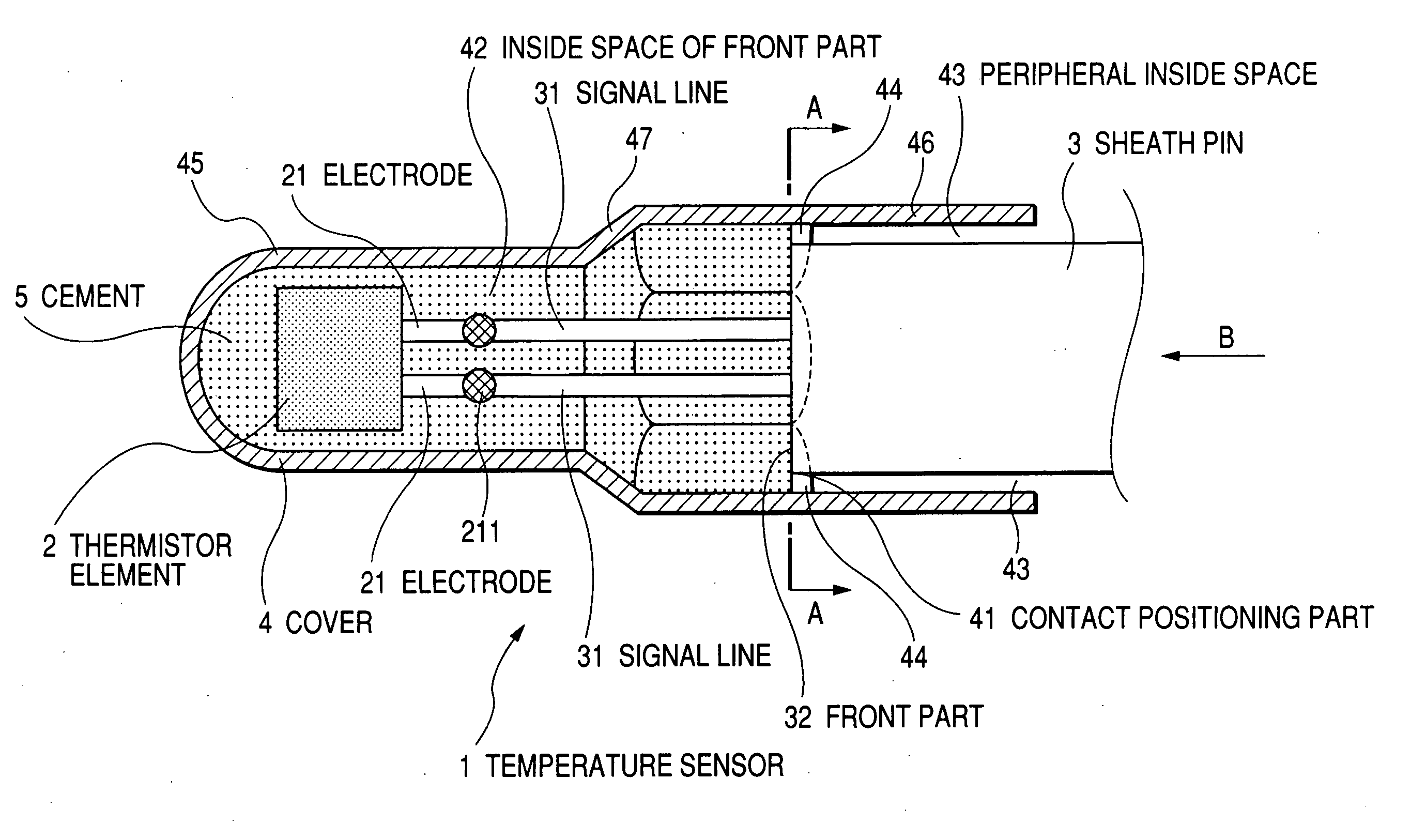
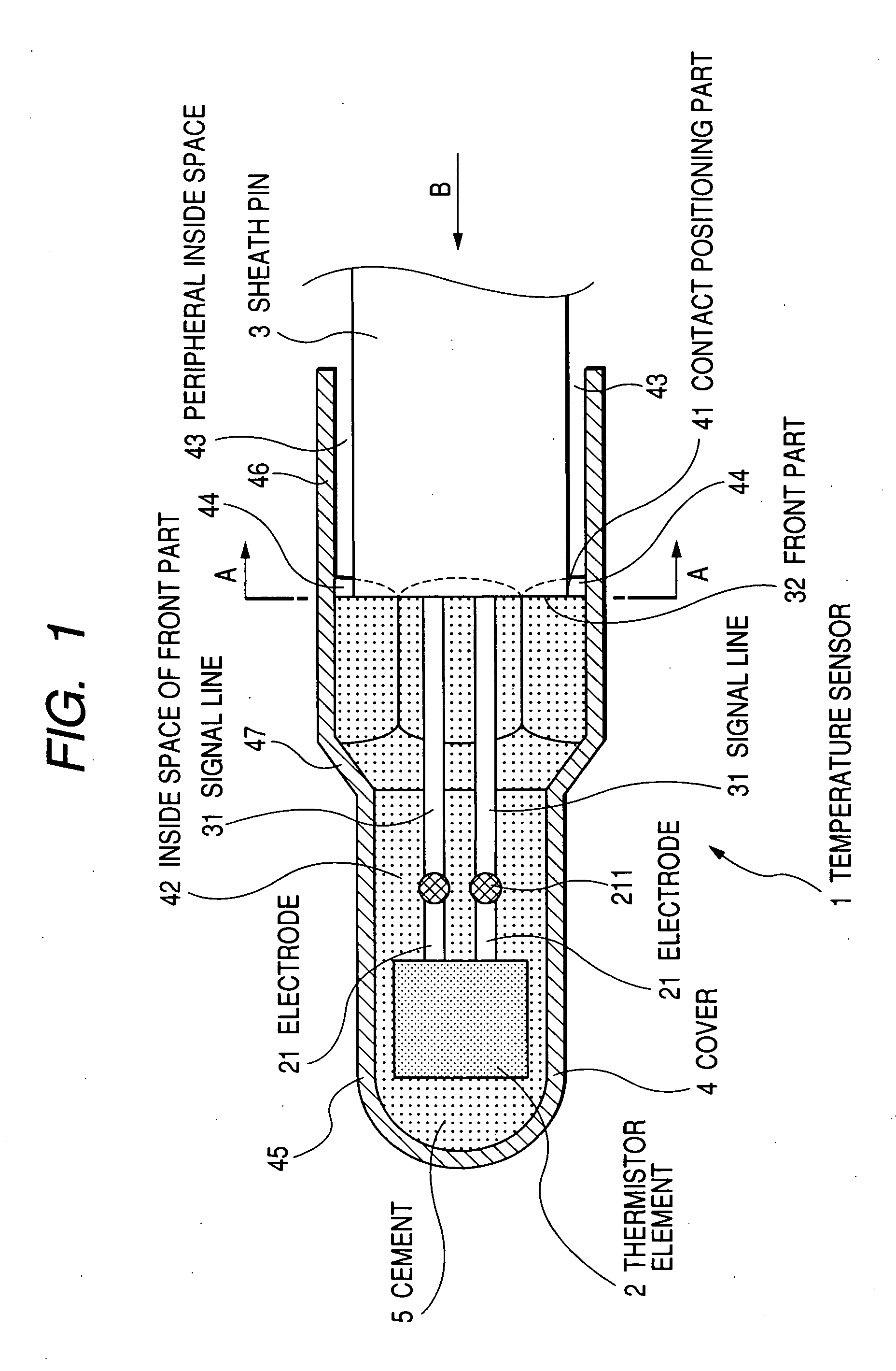
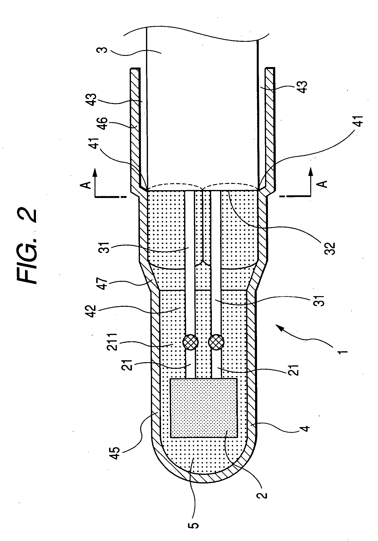
[0053]FIG. 1 is a sectional view showing a part near a front part of the temperature sensor 1 in the axis direction thereof according to the first embodiment. FIG. 2 is another sectional view showing the area near the front part of the temperature sensor 1 in the axis direction thereof. FIG. 3 is a view showing only a cover 4 placed at a front part of the temperature sensor 1 of the first embodiment, observed from the direction indicated by the arrow B shown in FIG. 1. FIG. 6 is a sectional view of the temperature sensor 1 in the axis direction according to the first embodiment.

[0054] As shown in FIG. 1, FIG. 2, and FIG. 6, the temperature sensor 1 has a thermistor element 2, a sheath pin 3, and a cover 4. The thermistor element 2 is composed of a pair of electrodes 21 (or electrode wires 21). In the sheath pin ...

Example

Second Embodiment

[0079] A description will be given of the temperature sensor according to the second embodiment of the present invention with reference to FIG. 9 to FIG. 12.

[0080]FIG. 9 is a sectional view of the area near the front part of the temperature sensor in the axis direction thereof according to the second embodiment of the present invention. FIG. 10 is another sectional view showing the area near the front part of the temperature sensor in the axis direction thereof according to the second embodiment. FIG. 11 is a view showing the cover 4 placed at a rear part of the temperature sensor 1 of the second embodiment, observed from the direction indicated by the arrow D shown in FIG. 9. Notice that FIG. 11 shows only the cover 4 observed from the direction indicated by the arrow D shown in FIG. 9. That is, the sheath pin 3 and the thermistor element 2 are omitted from FIG. 11.

[0081]FIG. 12 is a sectional view of the temperature sensor of the second embodiment along the lin...

Example

Third Embodiment

[0085] A description will be given of the temperature sensor according to the third embodiment of the present invention with reference to FIG. 13 to FIG. 15.

[0086]FIG. 13 is a sectional view of the area near the front part of the temperature sensor 1 in the axis direction of the third embodiment of the present invention. FIG. 14 is a view showing a cover placed at a rear part of the temperature sensor 1 of the third embodiment, observed from the direction indicated by the arrow F shown in FIG. 13. Notice that FIG. 14 shows only the cover 4 observed from the direction indicated by the arrow F shown in FIG. 13. The sheath pin 3 and the thermistor element 2 are omitted from FIG. 14.

[0087]FIG. 15 is a sectional view of the temperature sensor 1 of the third embodiment along the line E-E shown in FIG. 12.

[0088] Although the temperature sensor of the second embodiment shown in FIG. 12 has the plural concave parts 48, the temperature sensor of the third embodiment has on...


PUM


Abstract

A temperature sensor has a thermistor element equipped with a pair of electrodes, a sheath pin into which a pair of signal lines is built, and a cover surrounding the thermistor element. A front part of each signal line is exposed from the sheath pin. The cover is placed at a front part of the temperature sensor. The cover has a contact positioning part with which the front part of the sheath pin is contacted. Cement is filled into a space between the cover and the thermistor element in front of the front part of the contact positioning part. Through the cement, the thermistor element is supported by and fixed to the cover. A front inside space formed in front of the front part of sheath pin and a peripheral inside space formed in a rear side of the front part of the sheath pin are formed between the front part of the sheath pin and the inside surface of the cover.

Description

CROSS-REFERENCE TO RELATED APPLICATIONS [0001] This application is related to and claims priority from Japanese Patent Applications No. 2005-324672 filed on Nov. 9, 2005, and No. 2006-259972 filed on Sep. 26, 2006 the contents of which are hereby incorporated by reference. BACKGROUND OF THE INVENTION [0002] 1. Field of the Invention [0003] The present invention relates to a temperature sensor using a thermistor element. [0004] 2. Description of the Related Art [0005] There is a temperature sensor incorporating a thermistor element capable of measuring the temperature of an exhaust gas emitted from an internal combustion engine mounted on a vehicle. Japanese laid open publication NO. 2000-97781 had disclosed such a conventional temperature sensor incorporating a thermistor element whose resistance value is changed according to an ambient temperature change. [0006] Such a temperature sensor is composed of a thermistor element incorporating a pair of electrodes, a sheath pin incorporat...

Claims


Application Information

Patent Timeline
IPC IPC(8): G01K7/00G01K1/00
CPCG01K1/08G01K2205/04
Inventor TAKAHASHI, SOTOO
Owner DENSO CORP
Why Eureka
Try Eureka