
Equalizer and Equalizing Method thereof

Active Publication Date: 2007-05-10
REALTEK SEMICON CORP
View PDF11 Cites 15 Cited by
  • Summary
  • Abstract
  • Description
  • Claims
  • Application Information

AI Technical Summary

Benefits of technology

[0013] Therefore it is one of the objectives of the present invention to provide a Viterbi equalizer and equalizing method thereof, which can significantly reduce the amount of calculation of the Viterbi equalizer while maintaining efficiency.

Problems solved by technology

As a result, when the delay spread of the multipath channel becomes more severe, the length of the tapped delay line module increases accordingly, which translates to a drastic ramp in the complexity of the trellis tree.

Method used


Image

  • Equalizer and Equalizing Method thereof
  • Equalizer and Equalizing Method thereof
  • Equalizer and Equalizing Method thereof

Examples


Embodiment Construction

[0021] Certain terms are used throughout the following description and claims to refer to particular system components. As one skilled in the art will appreciate, consumer electronic equipment manufacturers may refer to a component by different names. This document does not intend to distinguish between components that differ in name but not function. In the following discussion and in the claims, the terms “including” and “comprising” are used in an open-ended fashion, and thus should be interpreted to mean “including, but not limited to . . . ” The terms “couple” and “couples” are intended to mean either an indirect or a direct electrical connection. Thus, if a first device couples to a second device, that connection may be through a direct electrical connection, or through an indirect electrical connection via other devices and connections.

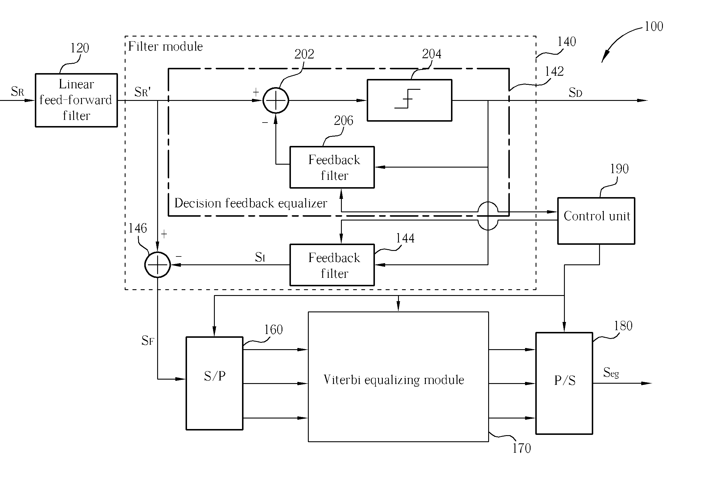
[0022] To further explain the present invention equalizer 100, please refer to FIG. 3. FIG. 3 illustrates a functional block diagram of an eq...


PUM


Abstract

An equalizer and an equalizing method for equalizing a received signal, where the received signal includes at least one primary interference and a plurality of secondary interferences. The Viterbi equalizer includes a filter module for filtering out the secondary interferences from the received signal to generate a filtered signal, a serial to parallel converter, coupled to the filter module, for generating a plurality of sequences according to the filtered signal, and a Viterbi equalizing module, coupled to the serial to parallel converter, for respectively equalizing the plurality of sequences to generate a plurality of equalized sequences. The architecture of the Viterbi equalizing module is greatly simplified thereby reducing the calculation activity of the Viterbi equalizer as well as maintaining its efficiency.

Description

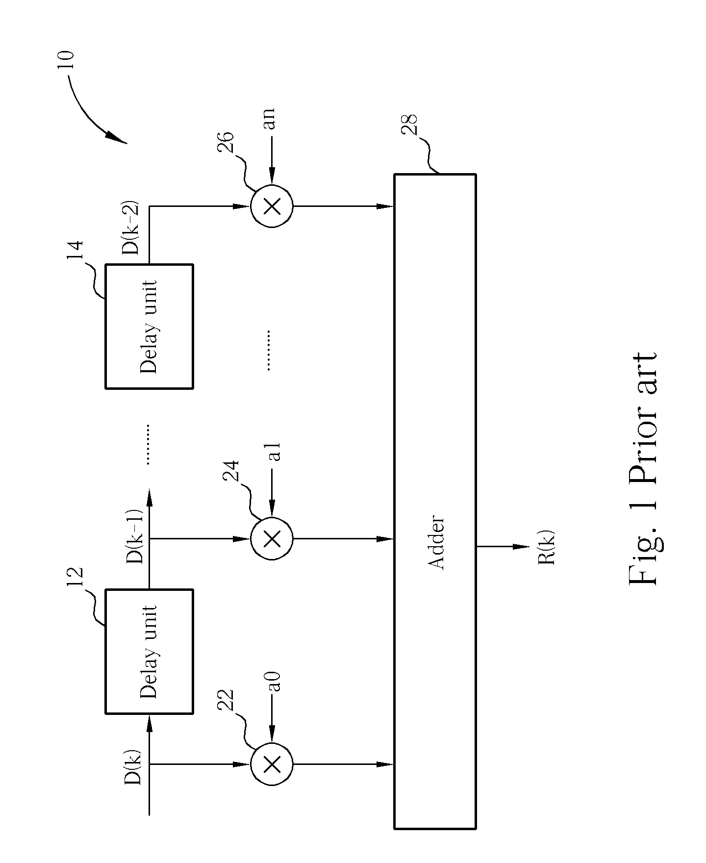
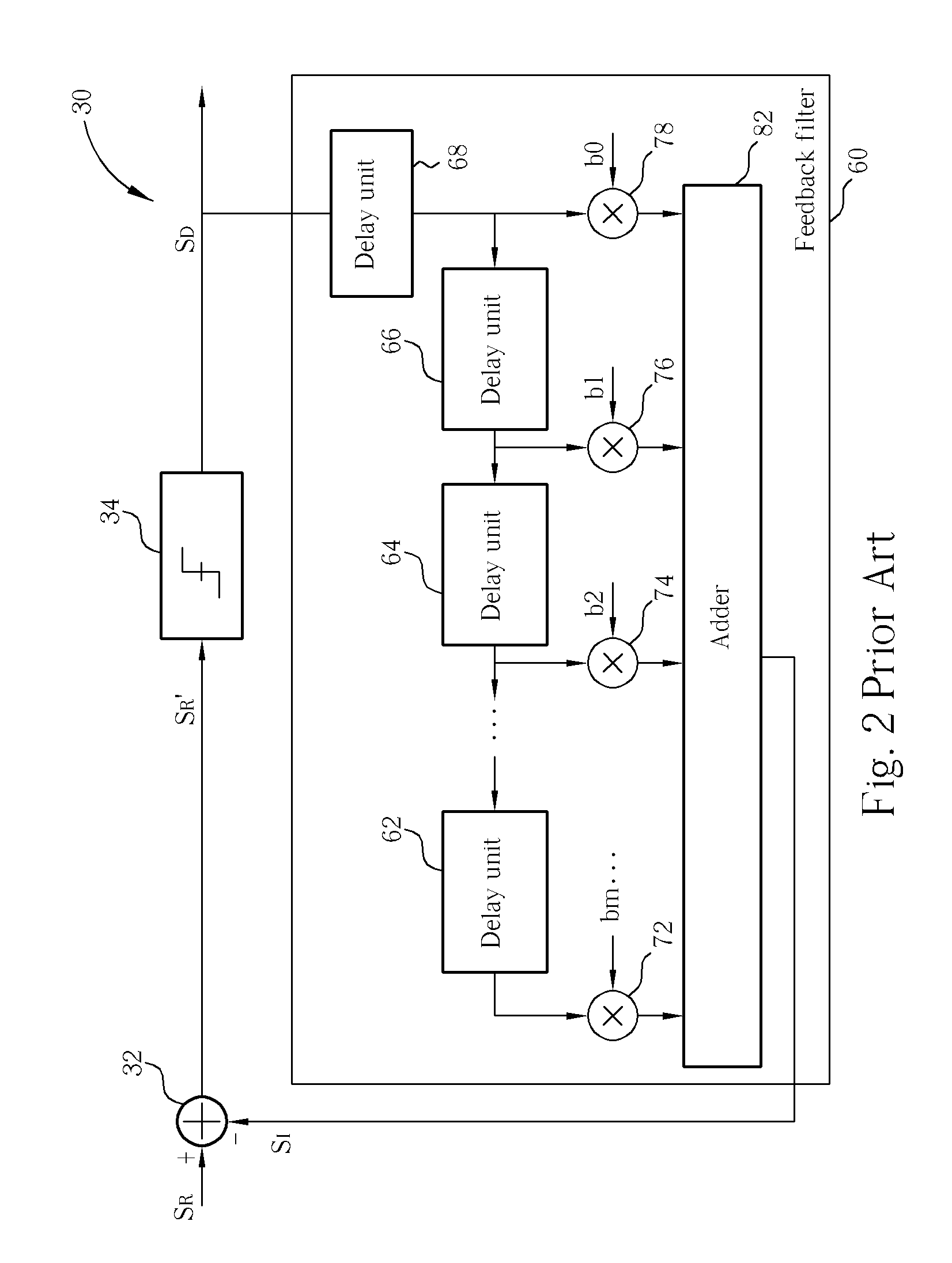
BACKGROUND OF THE INVENTION [0001] 1. Field of the Invention [0002] The present invention relates to an equalizer, and more particularly, to a Viterbi equalizer. [0003] 2. Description of the Prior Art [0004] In information systems, inter-symbol interference (ISI) is a common phenomenon. The primary cause of ISI is multipath propagation. For example, when a transmission end transmits a symbol D(1), the symbol D(1) may pass through different paths before arriving at a receiving end. Since the symbol D(1) passing through the different paths corresponds to different delayed times, the receiving end may detect energy of the symbol D(1) at different times. Hence, when the transmission end transmits sequentially, for example, a plurality of symbols D(2), D(3), D(4) . . . to the receiving end, the symbols can be affected by the previously transmitted symbol D(1). [0005] To further explain the multipath propagation phenomenon, please refer to FIG. 1. FIG. 1 illustrates a diagram of an equiva...

Claims


Application Information

Patent Timeline
IPC IPC(8): H03H7/30
CPCH03H21/0012H04L25/0328H04L25/03267H03H2021/0092
Inventor LIN, HOU-WEILI, YI-LINHUANG, CHENG-YIYEN, KUANG-YU
Owner REALTEK SEMICON CORP
Learn More