Water Cooling Type Heat Dissipation Apparatus with Parallel Runners

a heat dissipation apparatus and water cooling technology, applied in the direction of cooling/ventilation/heating modification, semiconductor/solid-state device details, etc., can solve the problems of inability to heat up, serious heat dissipation problems in integrated circuits, and other components of computers such as chipsets, graphics processors, and hard disk modules to produce considerable heat. , to achieve the effect of sufficient heat exchange and enhanced heat dissipation

Inactive Publication Date: 2007-05-17
COOLER MASTER CO LTD
View PDF4 Cites 26 Cited by
  • Summary
  • Abstract
  • Description
  • Claims
  • Application Information

AI Technical Summary

Benefits of technology

[0008] The present invention intends to provide a heat dissipation apparatus with multiple parallel runners defined by a plurality of heat dissipation fins and heat conduction post. Heat is absorbed by the heat conduction post and is conducted to the heat dissipation fins. Liquid coolant flows through the runners and is resisted by the heat conduction post. Therefore the liquid coolant stays longer in the runners and has sufficient heat exchange with the heat dissipation fins to enhance heat dissipation effect.

Problems solved by technology

Heat generation is inevitable for any electronic device due to friction and efficiency problem.
Some integrated circuits have serious heat dissipation problem for their compact size.
Besides CPU, other components in computer such as chipset, graphic processor, DRAM and hard disk module will also produce considerable heat.
However, the electrical fan can generated limited wind amount.
Multiple electrical fans can be used to increase wind amount, however, it will occupy more space.
Moreover, noise generates when the rotational speed of the electrical fan is increased.

Method used


Image

  • Water Cooling Type Heat Dissipation Apparatus with Parallel Runners
  • Water Cooling Type Heat Dissipation Apparatus with Parallel Runners
  • Water Cooling Type Heat Dissipation Apparatus with Parallel Runners

Examples


Embodiment Construction

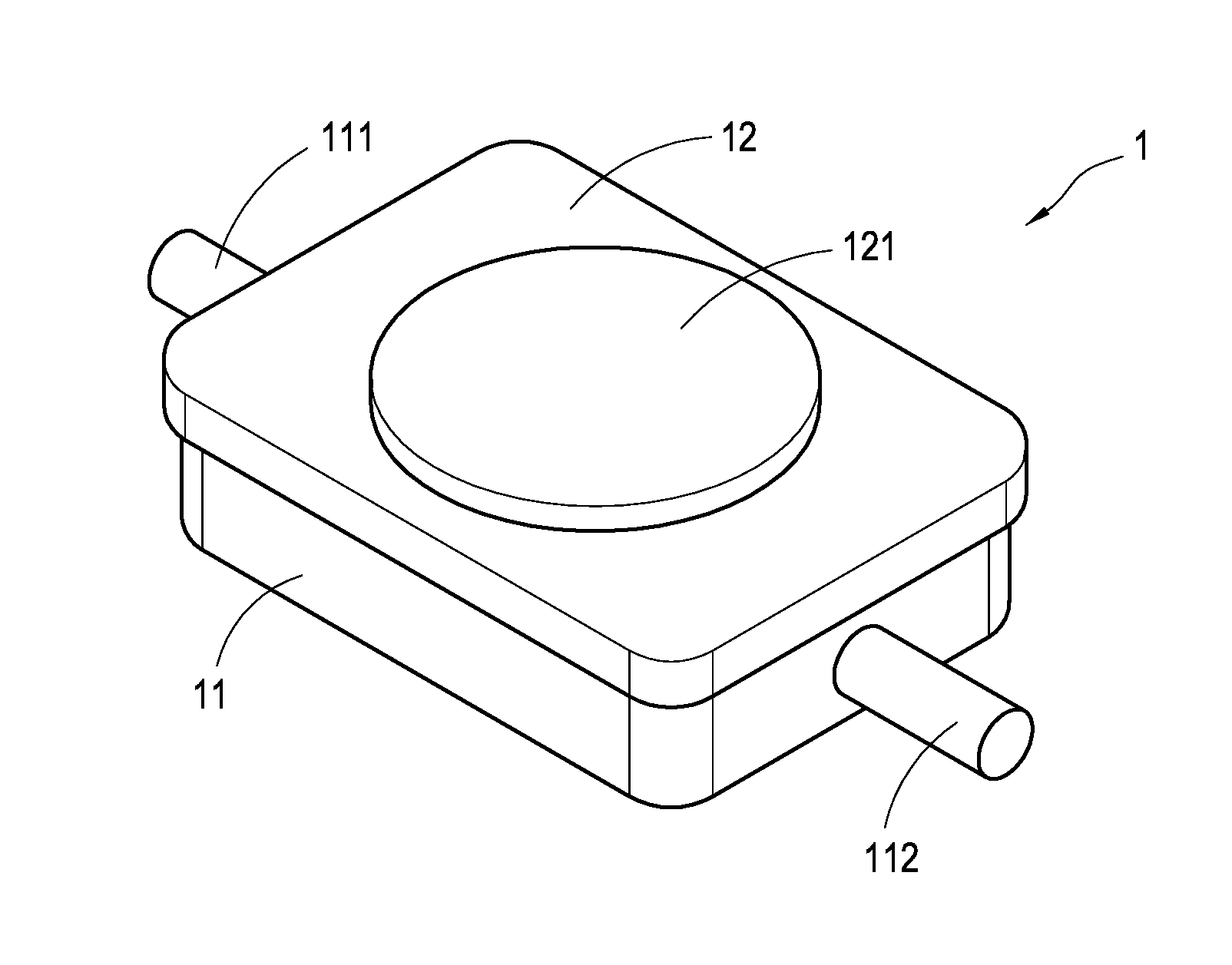
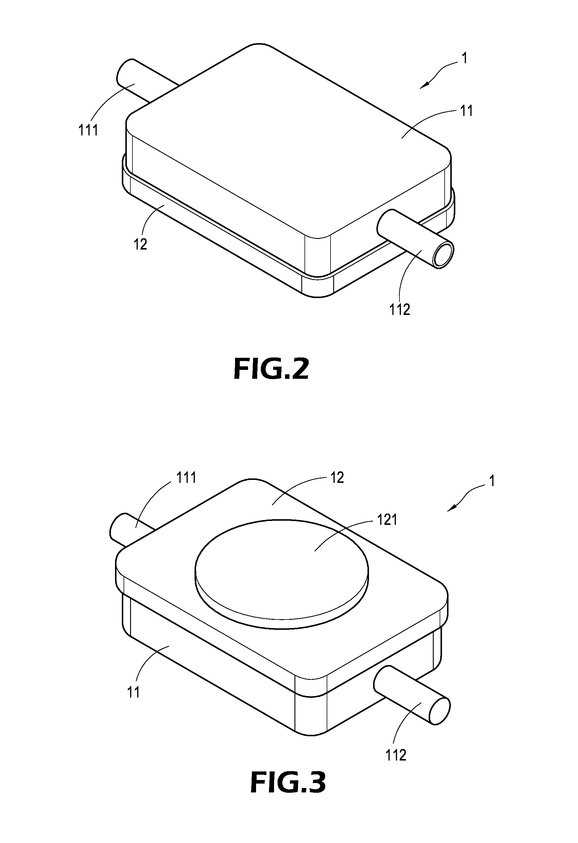
[0017] With reference to FIGS. 2 to 4, the heat dissipation stage 1 of the present invention comprises an upper cover 11 and a lower cover 12 to form a hollow closed box. The shape of the heat dissipation stage 1 of the present invention can be various according to practical need. In this shown preferred embodiment, the upper cover 11 and the lower cover 12 are of (but not limited to) rectangular shape, and made of heat conduction material such as metal or ceramics. The upper cover 11 and the lower cover 12 are assembled by soldering, riveting or bounding. Moreover, the upper cover 11 comprises a concave 113 on inner side thereof and a first passageway 111 and a second passageway 112 on left side and right side thereof (or upper side) for providing channel for liquid coolant to enter or exit the heat dissipation stage 1. The lower cover 12 comprises a contact face 121 on bottom side thereof and used for contacting the heat source.

[0018] The lower cover 12 comprises at leas one heat...


PUM


Abstract

A water cooling type heat dissipation apparatus includes a heat dissipation stage having an upper cover and a lower cover. A first passageway and a second passageway extend from two ends of the upper cover. The upper cover includes a concave on inner side thereof. The lower cover includes a contact face and a heat conduction post arranged on inner bottom side of the lower cover. A plurality of heat dissipation fins is arranged on the heat conduction post and separated to each other to define parallel runners therebetween. Heat from heat source is absorbed by the contact face and conducted to the heat conduction fins through the heat conduction post. Liquid coolant flows into the parallel runners through the first passageway and resisted by the heat conduction post. Therefore, liquid coolant has sufficient heat exchange with the heat conduction fins and then exits through the second passageway.

Description

BACKGROUND OF THE INVENTION [0001] 1. Field of the Invention [0002] The present invention relates to a heat dissipation structure, especially to a water cooling type heat dissipation structure for an electronic device. [0003] 2. Description of Prior Art [0004] Heat generation is inevitable for any electronic device due to friction and efficiency problem. Some integrated circuits have serious heat dissipation problem for their compact size. Moreover, computer will generate more heat as the performance thereof is increased. Besides CPU, other components in computer such as chipset, graphic processor, DRAM and hard disk module will also produce considerable heat. Therefore, heat dissipation devices are necessary to remove heat from computer and to ensure normal operation of computer. [0005] For example, electrical fan is often used as heat dissipation device and wind is generated by the electrical fan to remove heat from computer. However, the electrical fan can remove heat from a cont...

Claims


Application Information

Patent Timeline
Patent Type & Authority Applications(United States)
IPC IPC(8): H05K7/20
CPCH01L23/473H01L2924/0002H01L2924/00
Inventor PENG, YU-HUANG
Owner COOLER MASTER CO LTD
Why Eureka
Try Eureka