Flush mounted tubular patch

a tubular patch and flush mount technology, applied in the field of tubular patches, can solve the problems of increasing difficulty, increasing difficulty, and increasing difficulty, and achieving the effect of improving the stability of the patch, and increasing the difficulty of installation

Inactive Publication Date: 2007-05-17
BAKER HUGHES INC
View PDF20 Cites 7 Cited by
  • Summary
  • Abstract
  • Description
  • Claims
  • Application Information

AI Technical Summary

Benefits of technology

[0005] Casing or other well tubulars that have failed are repaired in a manner that doesn't reduce the final inside diameter and doesn't further propagate the failure. The tubular needing repair is first expanded on at least one zone above and below the damaged area. This expansion in an undamaged area arrests failure propagation when the damaged area is then expanded. After the damaged area is expanded, the patch coupled preferably with exterior seals is positioned in the expanded zone of the damaged tubular and expanded. The procedure can also be accomplished in a single trip into the well.

Problems solved by technology

This process can work but it is extremely time consuming and could get very expensive if ultimately it doesn't work in a particular application.
The cement is brittle and can break over time.
These types of patches are difficult to make in a short interval and progressively get more problematic with a longer interval.

Method used


Image

  • Flush mounted tubular patch
  • Flush mounted tubular patch

Examples


Embodiment Construction

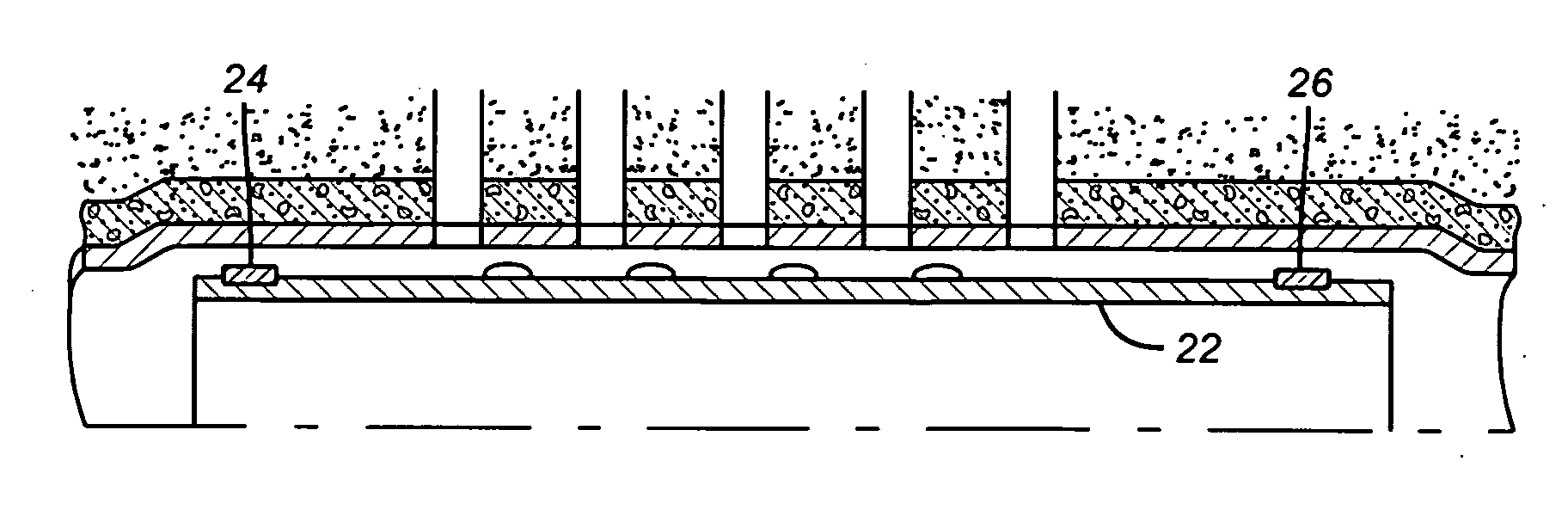
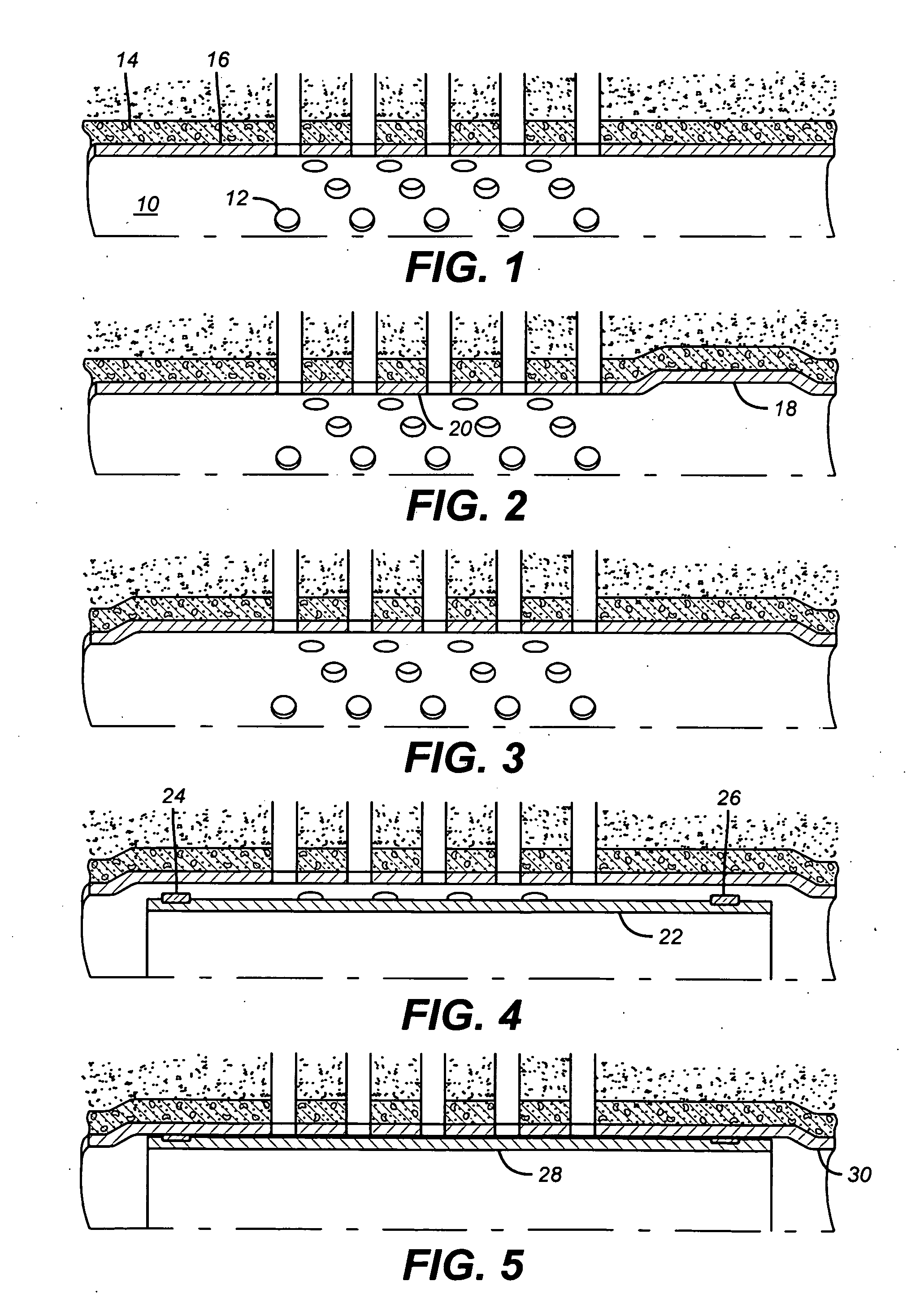
[0011]FIG. 1 shows a casing 10 that is either damaged itself or has damage in the adjacent perforations 12. There is cement 14 around the casing 10 in the wellbore 16. As a first step in the method an undamaged zone 18 is expanded. Zone 18 can be above the damaged area 20 or it can be below or it can be both above and below. Preferably, when expanding bottom up the zone 18 is uphole from the damaged area 20. Expanding

[0012] zone 18 will require expansion of the cement 14 and the formation 22 beyond it. The formation beyond can be rock that will expand but the higher the pore pressure, Young's modulus and Poisson's ratio, the harder will it be to accomplish the expansion. This makes formations with lower reservoir pressure, Young's modulus and Poisson's ratio more likely candidates for the method.

[0013] The reason an undamaged zone on either or both sides of a damaged zone is expanded first is that a failure or crack that defines the damaged zone will want to propagate if the damag...


PUM

PropertyMeasurementUnit
internal diameteraaaaaaaaaa
diameteraaaaaaaaaa
pressureaaaaaaaaaa

Abstract

Casing or other well tubulars that have failed are repaired in a manner that doesn't reduce the final inside diameter and doesn't further propagate the failure. The tubular needing repair is first expanded on at least one zone above and below the damaged area. This expansion in an undamaged area arrests failure propagation when the damaged area is then expanded. After the damaged area is expanded, the patch coupled preferably with exterior seals is positioned in the expanded zone of the damaged tubular and expanded. The procedure can also be accomplished in a single trip into the well.

Description

FIELD OF THE INVENTION [0001] The field of this invention is tubular patches applied by expansion and more particularly those that result in a flush mounting of the patch so that the internal diameter of the well is not reduced from patching. BACKGROUND OF THE INVENTION [0002] Downhole well tubulars sometimes develop leaks and need to be repaired. On technique to make such a repair is called cement squeezing. In this technique, cement is pumped into an isolated zone and hopefully into the damaged portions and the cement is allowed to set up. After setup the excess cement is drilled out of the wellbore and the repair is pressure tested to see if it has been successful. If it still fails to hold pressure the process can be repeated as many times as necessary until pressure integrity is regained. This process can work but it is extremely time consuming and could get very expensive if ultimately it doesn't work in a particular application. The cement is brittle and can break over time. ...

Claims


Application Information

Patent Timeline
Patent Type & Authority Applications(United States)
IPC IPC(8): E21B29/00
CPCE21B29/10Y10T29/49732E21B43/103
Inventor BAYCROFT, PERRY D.PETERSON, ELMER R.ROSENBLATT, STEVE
Owner BAKER HUGHES INC
Why Eureka
Try Eureka