However, the configuration of the ASTRID reactor is particularly unaccommodating insofar as there is a minimum of
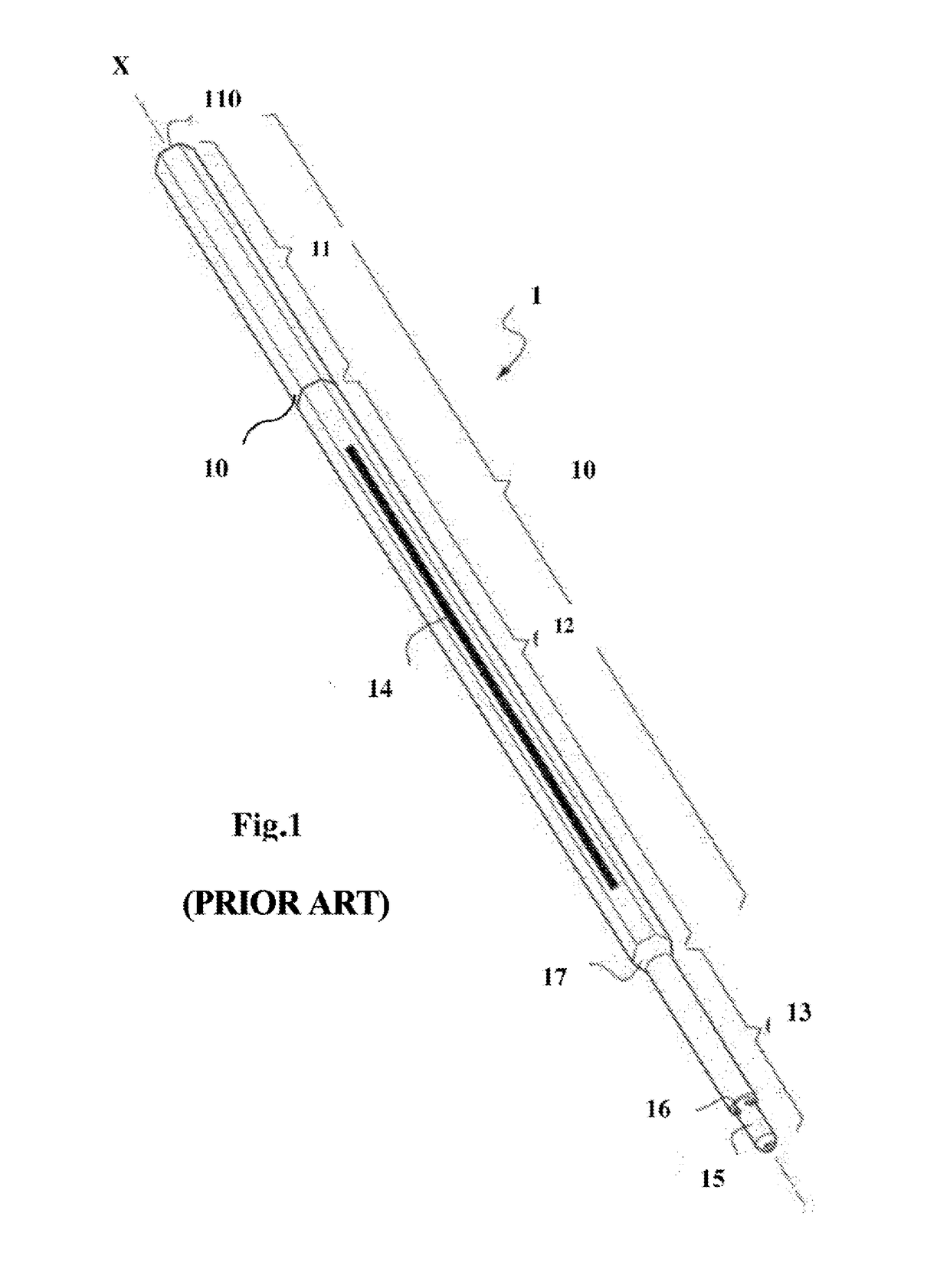
neutron flux absorbing structures between the top of the fissile fuel and the bottom of the UNS, i.e. structures such as the UAB structures (of substantial length) of the fuel assembly used in the Superphénix reactor.
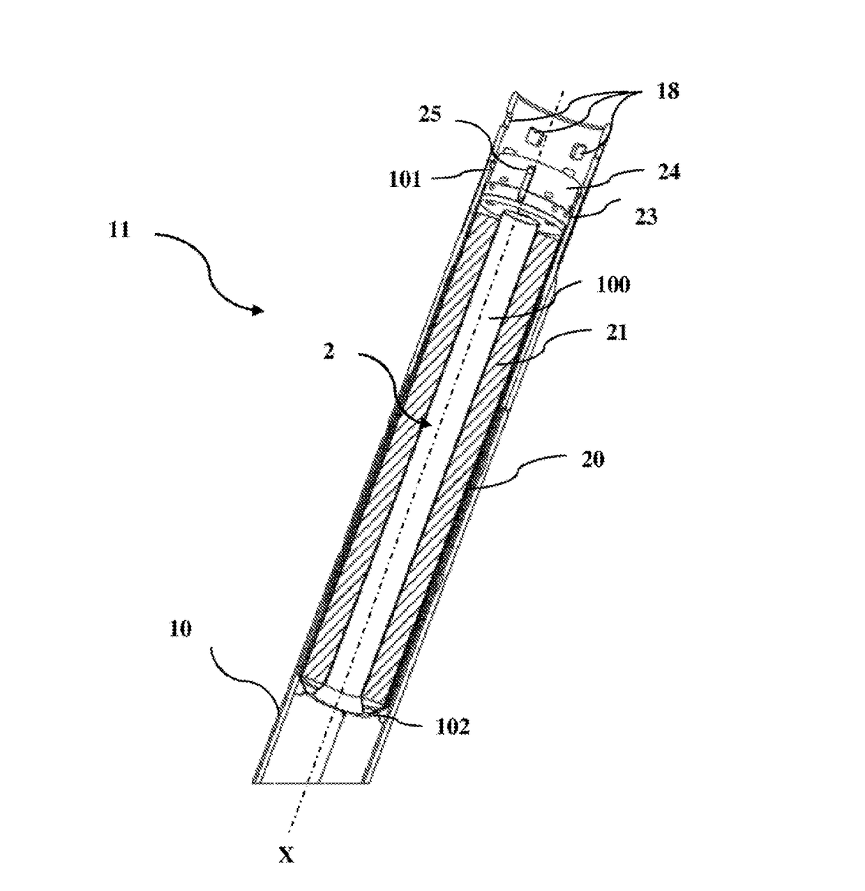
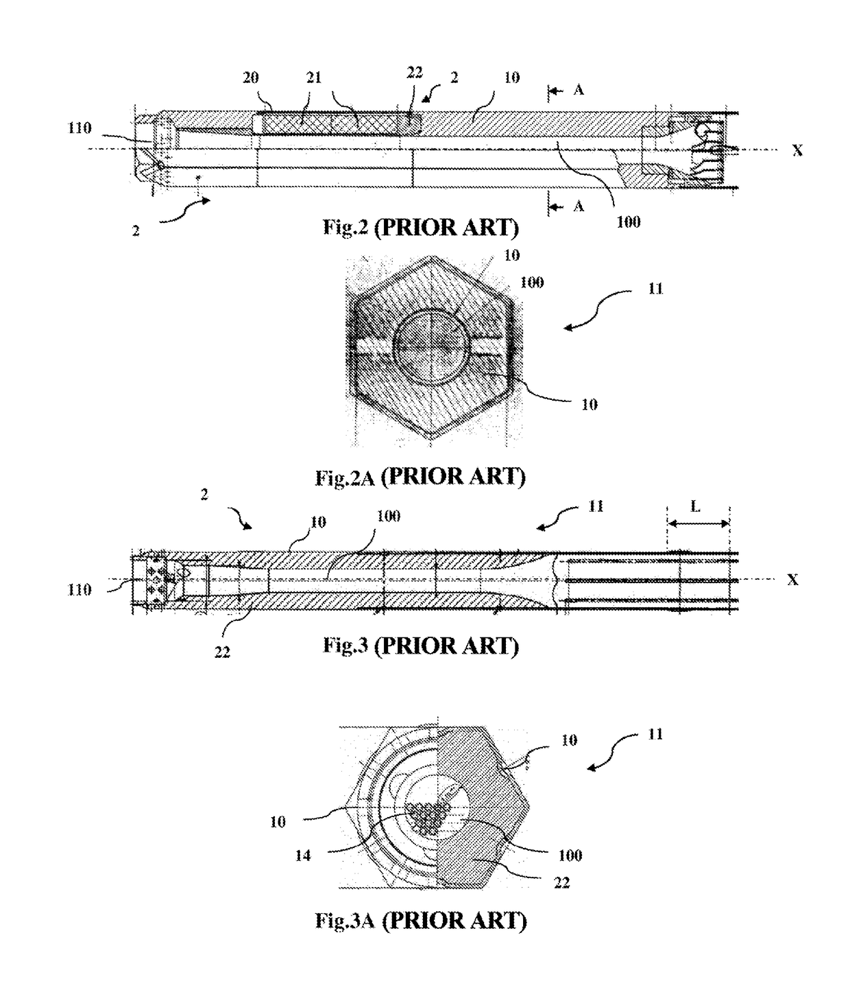
Under these conditions, the configuration of the Superphénix fuel assembly as illustrated in FIGS. 3 and 3A is unusable because the UNS 2, which is made of dense steel, would provide completely inadequate neutron shielding, unless the height of the UNS were greatly increased, which would be completely unacceptable for the height of the core of an ASTRID-type reactor.
If this coefficient is positive, voids result in an increase in the reactivity and in the power of the core.
However, such expansion vessels are unacceptable both in terms of bulk and in terms of safety.
Thus, increasing the height of a core by one meter in particular implies increasing the height of the vessel by two meters, leading to a significant increase in the required initial investment.
Furthermore, if there was a loss of containment of the substantial volumes of gas stored in the expansion vessels, there would then be a risk of rapid transients in core power.
When these known assemblies were dismantled, it is necessary to
chop up the irradiated assembly, this being an onerous
cutting operation that is very difficult to automate and that requires specific cells and pieces of equipment and very expensive additional storage spaces.
Specifically, none of the sodium-removing technologies studied up to now in R&D have given any reason to believe that it will be possible to obtain complete and effective sodium removal on an
industrial scale, this being incompatible with
pool storage such as provided for in the ASTRID reactor.
The presence of residual sodium in the UNS after washing, and more precisely in the play between the neutron absorbers and cladding, means that there is a risk of unexpected and uncontrolled reaction between the sodium and the water if the assemblies are stored in water long-term.
An assembly according to patent FR2402923 is incompatible with the functional specifications given above for a number of reasons.
Firstly, the handling head of the assembly is integral with the UNS and thus the assembly cannot be handled with the same gripper whether it is or is not equipped with its UNS.
In addition, the pin-based or bayonet connecting
system must bear the weight of the assembly during handling, this creating a
safety risk that is very hard to accept, namely the risk that the connection will break.
Lastly, the UNS cannot be demounted on-line and it is impossible to
handle the rest of the assembly once the UNS-head assembly has been removed.
Furthermore, the
capsule disclosed in this document, i.e. the
capsule containing the neutron absorbing material, is seal-tight and would require, under the operating conditions of the ASTRID fourth-generation SFR reactor, expansion vessels that would be very disadvantageous with respect to the height of the assembly and to the safety of the core.
In particular, it is completely unenvisionable to demount or remount on-line the screw threaded connections that are disclosed.
Moreover, even if these unscrewing and screwing operations were carried out in a handling flask, the inventors think that it would not actually be possible to ensure the reliability of these connections in a liquid-sodium-cooled reactor environment because of the multiple sources of deformation, of mechanical damage and of seizures after a long reactor stay, such as
irradiation swelling,
creep,
irradiation embrittlement, the mechanical loads applied to the head during handling operations, the sodium environment, etc.
This lack of reliability also goes for a bayonet connection between the assembly head and the shroud, because it is very hard to believe that this type of mechanical connection could reliably bear the load of the fuel assembly during handling.
In summary, the known solutions in the demountable UNS connections category are not suitable for the link between a UNS and the rest of an ASTRID fourth-generation SFR reactor fuel assembly, essentially for the following reasons:known connections are not demountable on-line;the fuel assemblies are necessarily handled via the UNS: the handling head of the assembly is extracted at the same time as the UNS, this meaning that it is no longer possible to
handle the assembly with the same gripper after the UNS has been extracted.
The known connections between the UNS and the assembly must therefore bear the weight of the assembly during handling, this creating a risk that is very hard to accept in terms of safety, namely the risk that the connection will break during handling.
Again, the solution proposed in Patent EP 0312416 does not allow the functional specifications (described above) for an ASTRID fourth-generation SFR reactor fuel assembly to be met.
Specifically, the disclosed locking
system firstly has too great an axial extent and the internal shoulder required in the assembly head implies too great a decrease in radial cross-section.
Furthermore, the disclosed
system under no circumstances allows the locking fingers to be mechanically forced in case of seizure.
Lastly, the pressure reducing device disclosed is handled by the same gripper as that used to
handle the assemblies and it is impossible to handle the assembly without having previously removed the pressure reducing device, this being incompatible with the level of availability expected for an industrial
nuclear reactor.
In other words, this lock does not allow ejection of a device, such as a removable UNS, under the drag force exerted by a
coolant to be prevented.
Moreover, in this patent, the return of the pivoting fingers is ensured by a spring, such a solution having no place in a
fast neutron reactor because it is not considered to be reliable, because of the risk of the elastic properties of the spring changing under
irradiation.
This system is not adapted to the on-line handling of heavy parts such as a UNS of a fuel assembly for a technology demonstrator such as ASTRID.
In summary, just like the known demountable UNS connections, the known locking systems of removable reactor devices analyzed above would not allow the specifications for the connection between a UNS and the rest of an ASTRID fourth-generation SFR reactor fuel assembly to be correctly met.


