Connection element for tubular heat exchanger

a technology of connection element and tubular heat exchanger, which is applied in the direction of tubular elements, indirect heat exchangers, lighting and heating apparatus, etc., can solve the problems of unfavorable and disruptive shadowing effects, and achieve the effect of advantageously influencing the effectivity, maintenance and operating times of tubular heat exchangers

Inactive Publication Date: 2011-10-27
KRONES AG
View PDF3 Cites 4 Cited by
  • Summary
  • Abstract
  • Description
  • Claims
  • Application Information

AI Technical Summary

Benefits of technology

[0021]By wav of example, the inside diameter of the through hole can continuously decrease between the inlet opening with the inside diameter d1 and the area of the flow separation edge with the inside diameter di outside of, particularly between, the respective part-circular indentations from the first inside diameter d1 to the inside diameter di. In this way, the inside diameter can behave in a manner similar to that in the previously described embodiment between the part-circular indentations (recesses), meaning in the area that is not recessed. Due to the steady change from the inside diameter d1 to the inside diameter di, it is possible in particular to concentrate the turbulence creation in the area of the flow separation edge. The steady, gentle change of the inside diameter of the connection element can thereby favor the flow control.
[0022]The disclosure furthermore provides a tubular heat exchanger with at least one heat exchanger element with a jacketed tube and at least one interior tube and with a connection element according to the disclosure, as described above. The advantage of such a tubular heat exchanger is the corresponding control and reduction of fiber deposits in the influx area in a heat exchanger element, which has a connection element according to the disclosure pre-arranged before it.
[0023]The disclosure furthermore provides a method for retrofitting a flow system with a tubular heat exchanger with at least one heat exchanger element and at least one product-carrying tube, comprising connecting of an end of the heat exchanger element with a connection element to a side of the connection element facing towards the heat exchanger element, and connecting of the connection element to the product-carrying tube on the side turned away from the heat exchanger element. By means of such a retrofitting method, the effectivity, maintenance and operating times of a tubular heat exchanger can be advantageously influenced.

Problems solved by technology

Detrimental in these known displacers, however, is that the manufacture of these displacers is complicated, they frequently must have complicated shapes that are different for facing towards and facing away from the product flow and that in particular, undesired and disruptive shadowing effects can also occur.

Method used


Image

  • Connection element for tubular heat exchanger
  • Connection element for tubular heat exchanger
  • Connection element for tubular heat exchanger

Examples


Embodiment Construction

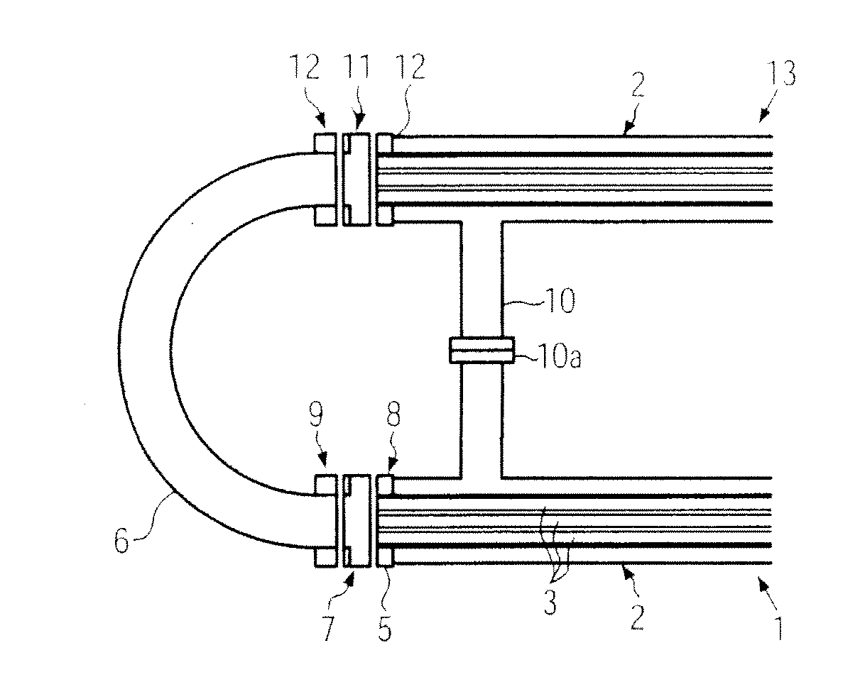
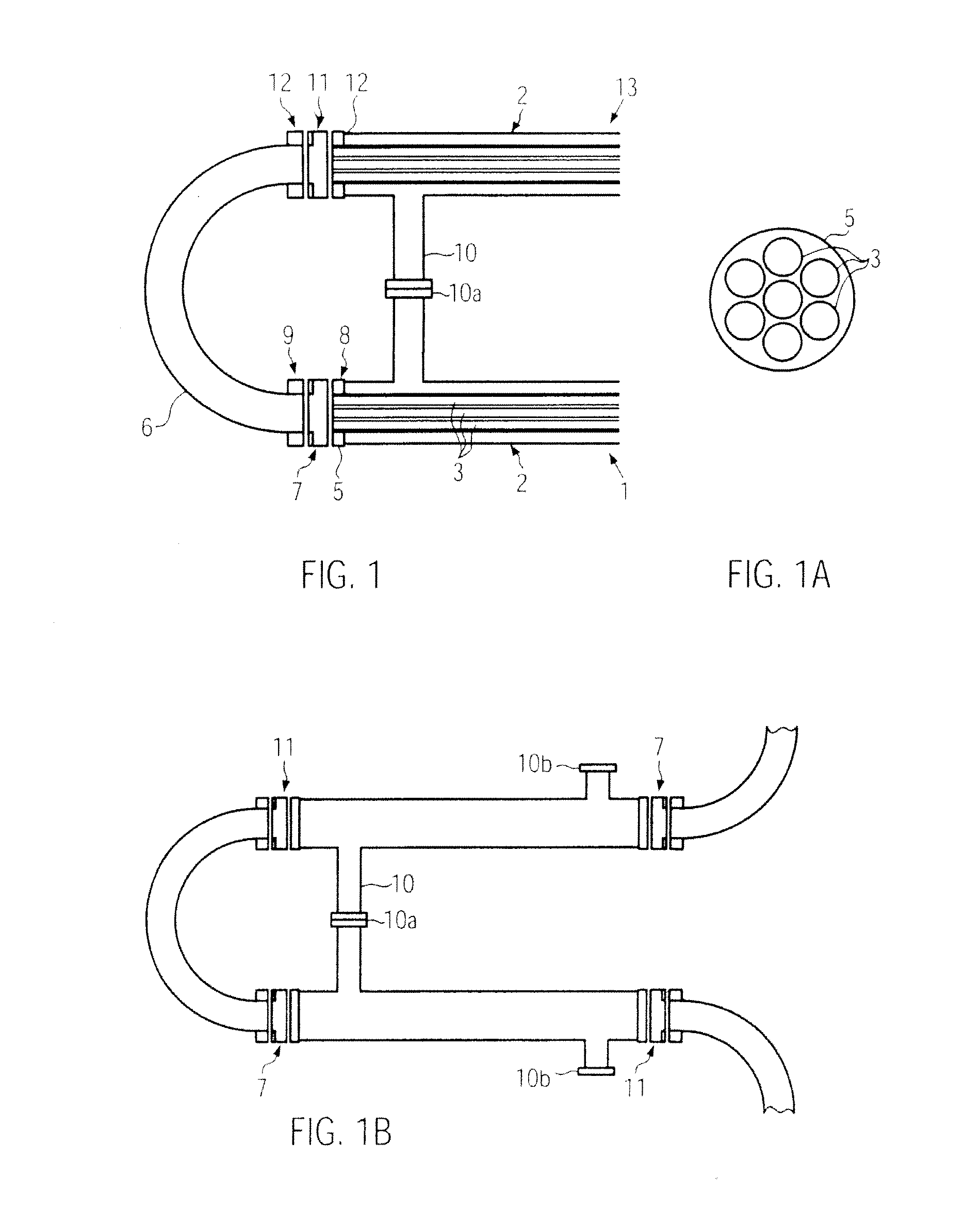
[0034]FIG. 1 illustrates a tubular heat exchanger with at least one heat exchanger element 1 and a further product-carrying tube 13 that are connected to a further product-carrying tube that is curved, namely a connection bend 6. The tubular heat exchanger with the at least one heat exchanger element 1, the product-carrying tube 13 and the connection bend 6 are of the type such as is used, for example, in the bottling and filling industry for liquid food products (e.g., water, juices, milk) during the heat treatment (heating or cooling) of a food product. A plurality of modules, namely heat exchanger elements 1, can be built into the tubular heat exchanger in order to achieve the longest possible flow paths for the product. The connection of the further product-carrying tube 13 to the connection bend 6 is executed in FIG. 1 by corresponding mourning flanges 12 at the ends. A connection element 11 is deployed for connection between the flanges 12 in FIG. 1. The connection element 11 ...


PUM

PropertyMeasurementUnit
angleaaaaaaaaaa
total lengthaaaaaaaaaa

Abstract

Connection element for connecting a heat exchanger element of a tubular heat exchanger with at least one product-carrying pipe to a flow system, where the connection element has a through hole, and a flow separation edge is formed on the circumference of the through hole.

Description

CROSS-REFERENCE TO RELATED APPLICATION[0001]The present application claims the benefit of priority of German Application No. 102010028117.4, filed Apr. 22, 2010. The entire text of the priority application is incorporated herein by reference in its entirety.FIELD OF THE DISCLOSURE[0002]The disclosure relates to a connection element for connecting a heat exchanger element of a tubular heat exchanger with at least one product-carrying tube to a flow system.BACKGROUND[0003]When tubular heat exchangers with one or more heat exchanger elements are used for fibrous products, it happens that the fibers block up the feed of a heat exchanger element in the area of the interior tubes that form the tube bundle, whereby these interior tubes form the flow channels for a product. In order to prevent this, it has already been proposed in the state of the art to arrange turbulence creators in the inflow channel in the middle of the inlet area in order to avoid deposits with the help of the turbulen...

Claims


Application Information

Patent Timeline
Patent Type & Authority Applications(United States)
IPC IPC(8): F28F1/00B23P15/26
CPCF28D7/16Y10T29/49391F28F13/06F28F9/26
Inventor JUSTL, JOHANNPORRINGER, MICHAEL
Owner KRONES AG
Why Eureka
Try Eureka