Conductor pipe string deflector and method

a technology of conductor pipe and deflector, which is applied in the direction of drilling pipes, well accessories, sealing/packing, etc., can solve the problems of inconvenient installation, inconvenient deflection of tubular string, and inability to meet the requirements of a single vessel, etc., and achieves the effect of reducing the cost of installation

Inactive Publication Date: 2009-02-03
FRANKS INT
View PDF30 Cites 5 Cited by
  • Summary
  • Abstract
  • Description
  • Claims
  • Application Information

AI Technical Summary

Benefits of technology

[0008]An apparatus for deflecting a tubular having a tubular wall comprising an aperture in the tubular wall, and a nozzle mounted within the aperture in the tubular wall. The nozzle is an integral part of the tubular wall. The nozzle has a progressively decreasing inside diameter for defining a progressively converging flow path such that any fluid passing through the progressively converging flow path has a velocity that increases as the fluid passes through the progressively converging flow path. Such flow causes the static pressure exerted by the fluid to decrease, the velocity to increase and the ram pressure to increase. The ram pressure increases to a maximum pressure as the fluid exits the nozzle. The fluid moving through the tubular is directed through said nozzle, and the fluid moving through the nozzle creates a jet flow with a maximum ram pressure which deflects the tubular in a direction substantially opposite the direction of the fluid flow through said nozzle.

Problems solved by technology

Subsea production systems can range in complexity from a single satellite well with a flowline linked to a fixed platform or an onshore installation, to several wells on a template or clustered around a manifold, and transferring to a fixed or floating facility, or directly to an onshore installation.
Deep water conditions, or even ultra-deep water conditions, can also inherently dictate development of a field by means of a subsea production system, because traditional surface facilities such as on a steel-piled jacket, might be either technically unfeasible or uneconomical due to the water depth.
The deployment of such equipment requires specialized and expensive vessels, which need to be equipped with diving equipment for relatively shallow equipment work, i.e., a few hundred feet water depth maximum, and robotic equipment for deeper water depths.
Any requirement to repair or intervene with installed subsea equipment is thus normally very expensive.
This type of expense can result in economic failure of the subsea development.
The pipe lowering operation is difficult for various identifiable reasons.
Obviously, there is a problem in getting the bottom end of the pipe string or drill string to hit the mouth of the well bore.
The problem is further complicated by the fact that a string of pipe having a length of several hundred or several thousand feet is flexible and is readily subject to being deflected by movement of the vessel or underwater currents.
There are no satisfactory means of directing the bottom end of a string of pipe to the mouth of a subbottom well bore, other than by moving the surface ship or platform and rotating the pipe in the hope that the pipe string and the mouth of the well bore will come into alignment with one another.
As a consequence, directing the bottom end of a string of pipe to the mouth of a subbottom well bore is very time consuming at best and may, in some cases, be impossible to accomplish.

Method used


Image

  • Conductor pipe string deflector and method
  • Conductor pipe string deflector and method
  • Conductor pipe string deflector and method

Examples


Embodiment Construction

[0030]It should be understood that the description herein below may use the terms drill string, pipe string, or the more general term tubular or tubular string interchangeably without intention of limitation. It should be further understood that the device and method described herein can be applied to tubulars other than drill string, casing, or tubing.

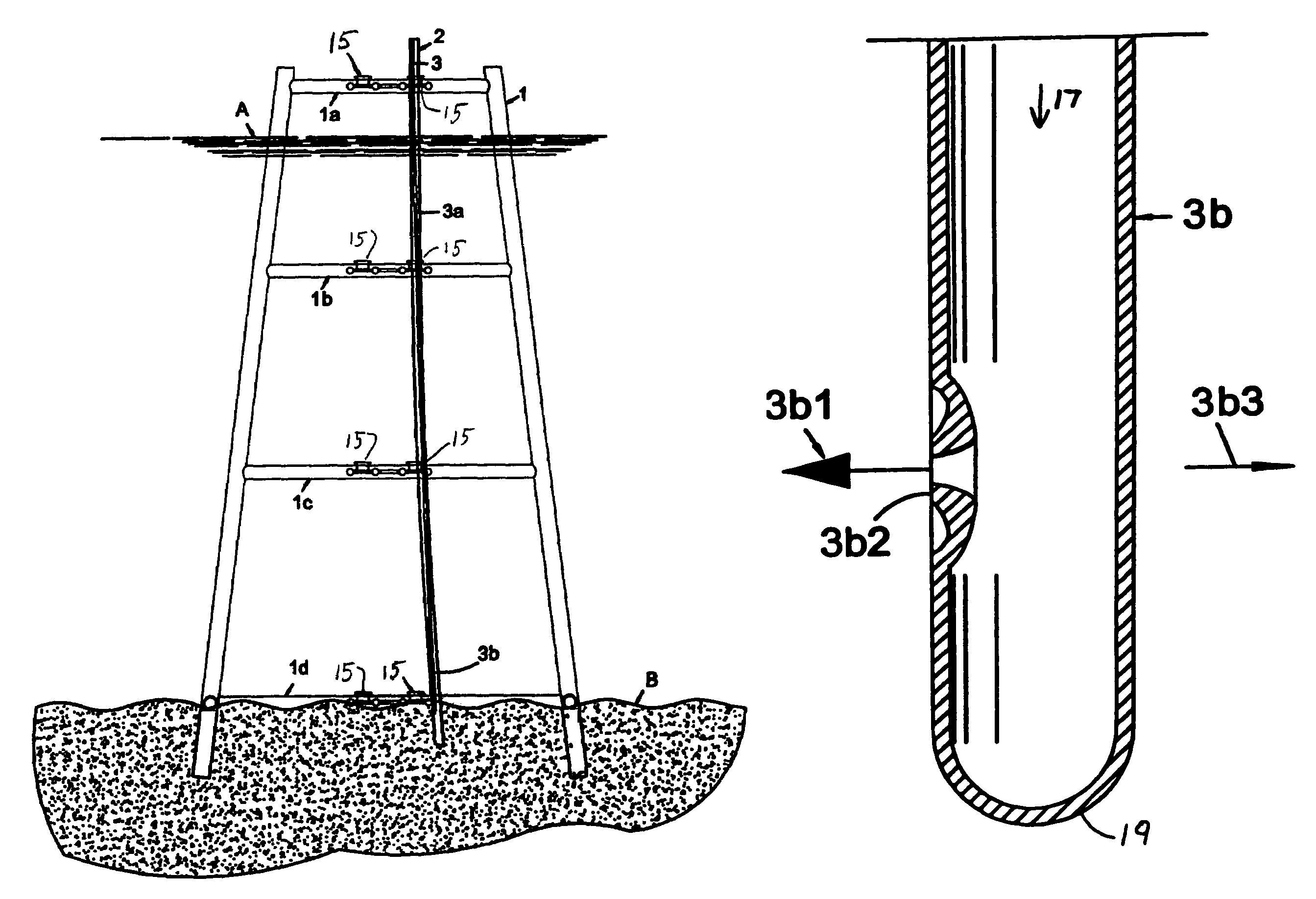
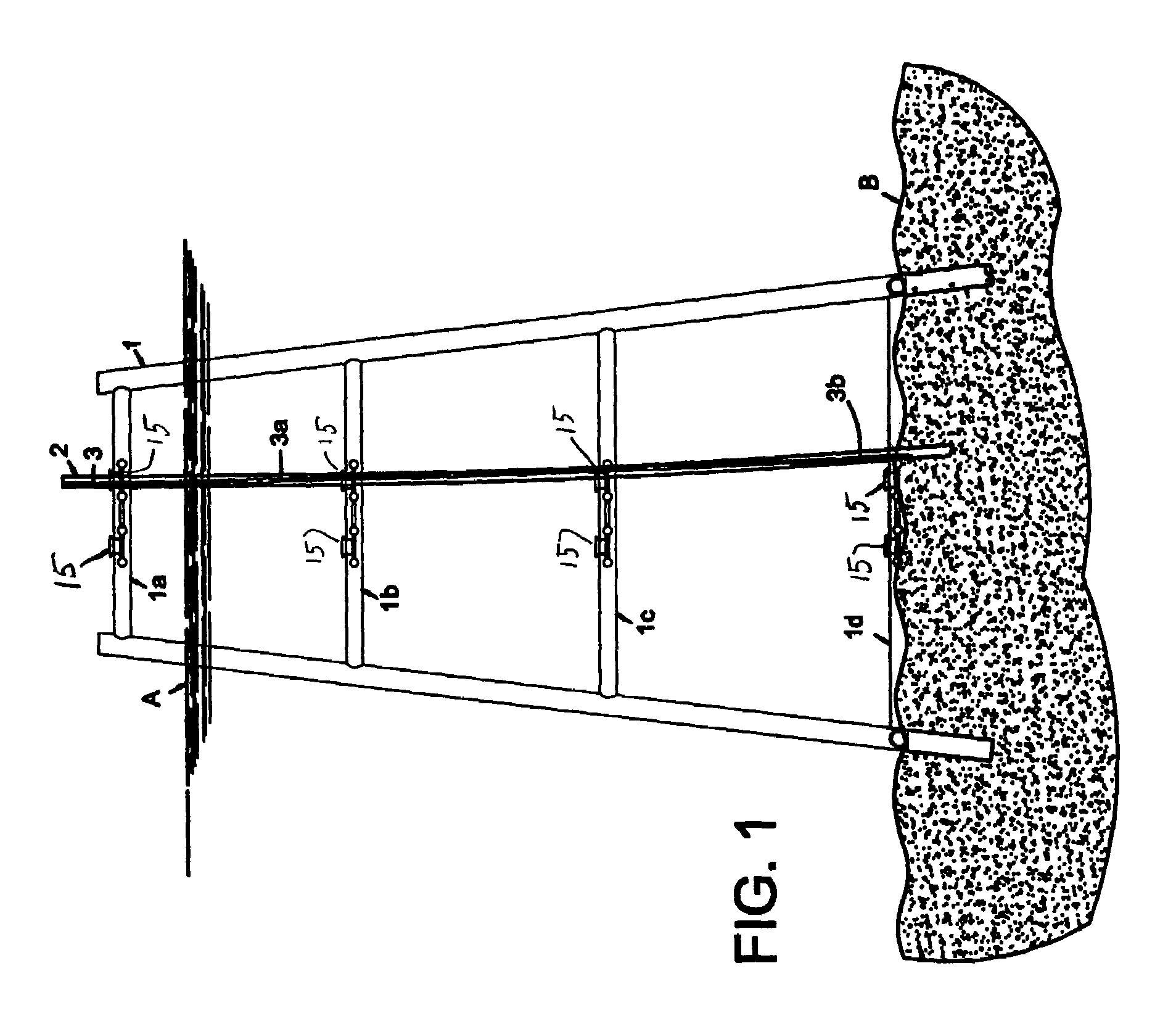
[0031]FIG. 1 illustrates the lower portion of a typical fixed offshore platform 1. It is well known in the art that the platform structure stands in the seabed B, is preferably anchored in a conventional manner, and preferably has vertically distributed braces such as illustrated by braces 1a-d. It is further well known that the platform comprises a plurality of “slots” through which one or more wells can be drilled. Typically, guide sleeves 15 are mounted to the braces 1a-1d and are substantially vertically aligned with the “slots”. Typically, tubulars, used for drilling and production operations are lowered through the “slots” and t...


PUM


Abstract

An apparatus for deflecting a tubular string preferably comprising at least one side nozzle near the lower end of a first tubular string. The nozzle permits passage of a fluid therethrough from the first tubular string bore and deflects the first tubular string in a substantially horizontal direction. A second tubular string may be lowered over the deflected first tubular string. The second tubular string and the first tubular string are preferably lowered into the sea floor for maintaining their deflection. A method for deflecting a first tubular string and securing the first tubular string in the deflected state preferably comprises lowering the first tubular string axially so that the lower end of the first tubular string is near the sea floor. Preferably, a fluid, such as seawater, is propelled down through the bore of the first tubular string and through at least one side nozzle near the lower end of the first tubular, wherein the fluid moving through the side nozzle deflects the first tubular string. The first tubular string end is preferably lowered into the sea floor for maintaining the deflection of the first tubular string. A second tubular string may then be slidably lowered over the first tubular string for deflecting the second tubular string.

Description

FIELD OF THE INVENTION[0001]This invention pertains to apparatus and method for the deflection of a tubular string which may be suspended from a drilling or service rig or platform.BACKGROUND OF THE INVENTION[0002]Subsea production systems can range in complexity from a single satellite well with a flowline linked to a fixed platform or an onshore installation, to several wells on a template or clustered around a manifold, and transferring to a fixed or floating facility, or directly to an onshore installation. Subsea production systems can be used to develop reservoirs, or parts of reservoirs, which require drilling of the wells from more than one location. Deep water conditions, or even ultra-deep water conditions, can also inherently dictate development of a field by means of a subsea production system, because traditional surface facilities such as on a steel-piled jacket, might be either technically unfeasible or uneconomical due to the water depth.[0003]Subsea hydrocarbon. e.g...

Claims


Application Information

Patent Timeline
Patent Type & Authority Patents(United States)
IPC IPC(8): E21B7/18
CPCE21B7/043E21B7/065E21B41/0014E21B7/12
Inventor ANGELLE, JEREMY R.BRASSEUX, GUY R.
Owner FRANKS INT
Why Eureka
Try Eureka