Induction heating of springs

a technology of induction heating and springs, which is applied in the direction of electric/magnetic/electromagnetic heating, heat treatment apparatus, furnaces, etc., can solve the problems of adversely altering the micro-structure of the spring, overheating the end portions of the spring, etc., and achieves the effect of shortening the time duration

Active Publication Date: 2014-12-18
BARNES GROUP
View PDF15 Cites 3 Cited by
  • Summary
  • Abstract
  • Description
  • Claims
  • Application Information

AI Technical Summary

Benefits of technology

[0009]In one non-limiting aspect of the present invention, there is provided a novel induction coil configuration for the induction coil. The induction coil is generally a liquid cooled induction coil; however, the induction coil can be cooled by other or additional means. In one non-limiting embodiment of the invention, the induction coil is positioned on two sides of the spring along at least a portion of the longitudinal length of the spring. As can be appreciated, the coils of the induction coil can be positioned on more than two sides of the spring. Generally, the induction coils are spaced at a generally constant distance from one another along at least a portion of the longitudinal length of the spring. Typically, the induction coils are spaced at a generally constant distance from one another along the complete longitudinal length of the spring. Many different induction coil configurations can be used to heat the spring. In one non-limiting design, the induction coil has a generally square or rectangular shape. In another non-limiting embodiment of the invention, the induction coil has a reducing inside-diameter with one or more turns. In such a configuration, at least two coils are positioned along at least a portion of the longitudinal length of the spring and at least one coil is positioned on an opposite side of the spring and along at least a portion of the longitudinal length of the spring. As can be appreciated for any of the induction coil configurations, a) the number of coils on each side of the spring can be the same or different, b) the length of the one or more coils on one or more longitudinal sides of the spring can be the same or different, c) the length of the one or more coils on one or more longitudinal sides of the spring can be the same or different, d) the length of one or more of the coils can be greater than, equal to or less than the longitudinal length of the spring, e) the cross-sectional area of the one or more coils along the longitudinal length of the coil can be constant or vary, f) the cross-sectional area of two or more coils can be the same or different, g) the spacing of one or more of the coils from the spring along the longitudinal length of the spring can be constant or vary, and / or h) two or more of the coils can lie in the same or parallel plane along a majority or all of the longitudinal length of the spring. In still another non-limiting embodiment of the invention, more than one induction coil can be used to heat the spring. The novel induction coil configuration enables eddy currents generated during induction heating of the spring to be focused into two highly concentrated “beams” of heating area, thereby producing an efficient heating of the spring. This heating effect, combined with natural conduction through the spring, provides consistent and rapid heating of the spring.
[0036]It is still another and / or alternative non-limiting object of the present invention to provide an induction heating arrangement wherein multiple springs have adjacently positioned ends that are sufficiently spaced apart from one another so as to inhibit or prevent undesired overheating of one or both ends of the springs.

Problems solved by technology

Rotation speeds that are too high have been found to result in overheating of the end portions of the spring during induction heating.
Such overheating can result in the welding together of portions of the end coils of the springs during induction heating and / or adversely alter the micro-structure of the spring.

Method used


Image

  • Induction heating of springs
  • Induction heating of springs
  • Induction heating of springs

Examples


Embodiment Construction

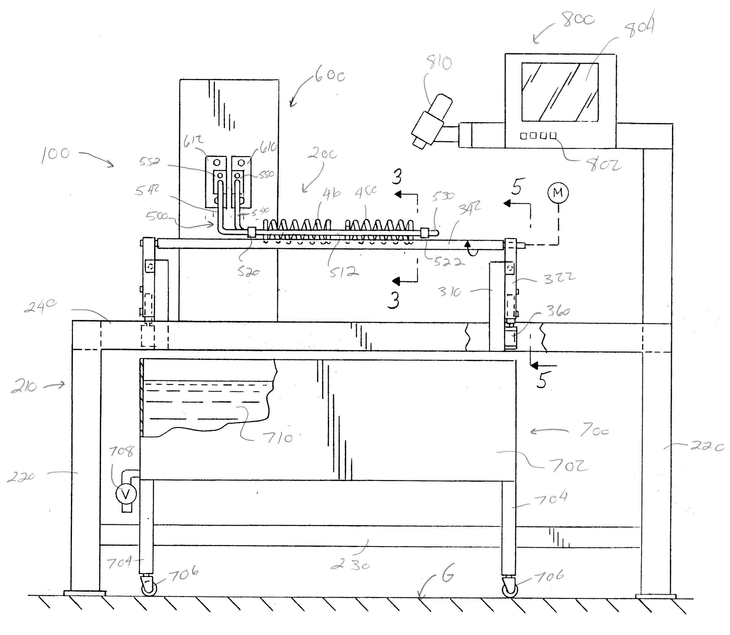
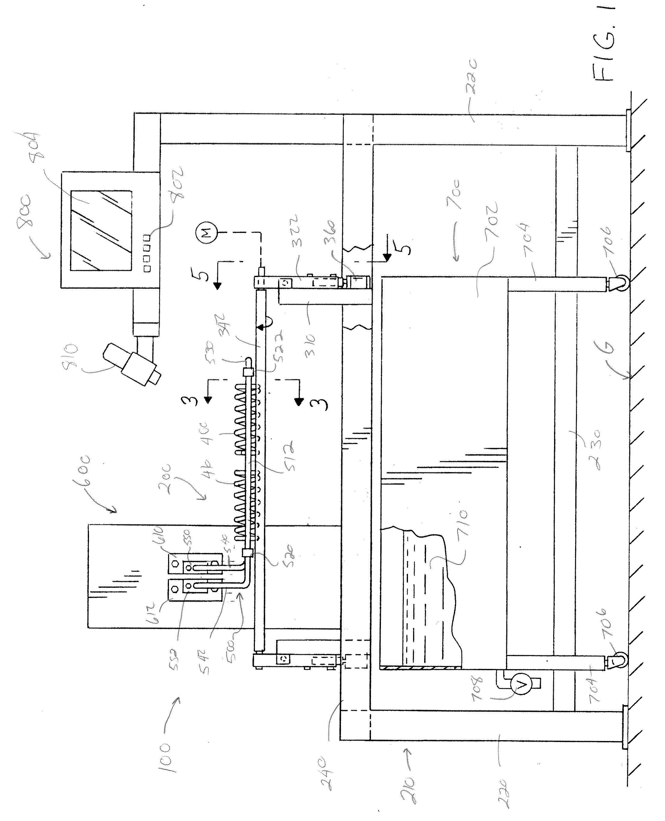
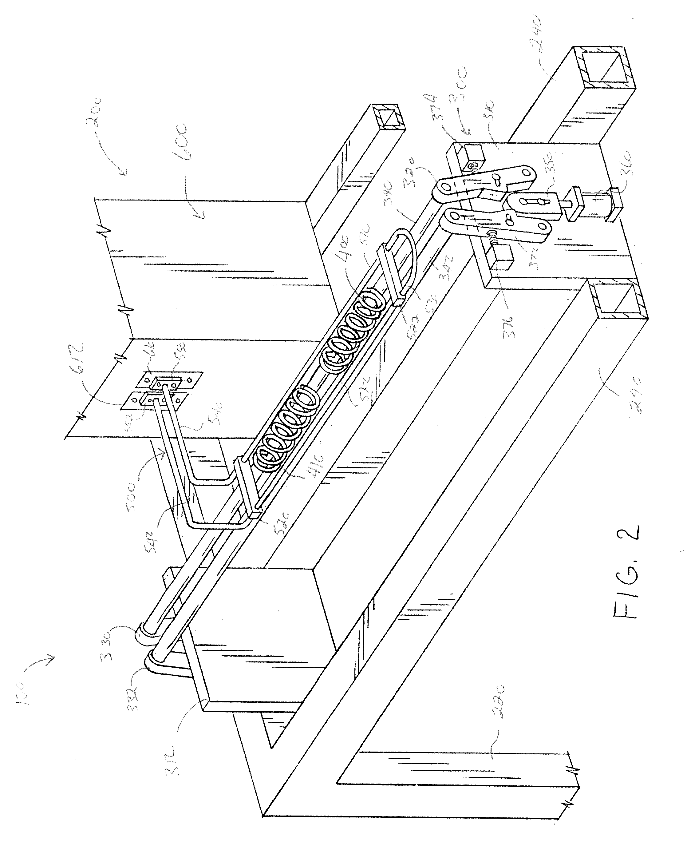
[0051]Referring now to the drawings wherein the showings are for the purpose of illustrating non-limiting embodiments of the invention only and not for the purpose of limiting same, FIGS. 1-6 illustrate one non-limiting processing arrangement 100 for heating and hardening a spring in accordance with the present invention. Processing arrangement 100 is illustrated as a batch process for heating and hardening one or more springs. As can be appreciated, processing arrangement 100 can be configured to heat and harden springs by a continuous non-batch process; however, this is not required. The springs that are heated and hardened by processing arrangement 100 are typically helical or beehive springs and the invention will be described with particular reference to such springs; however, it can be appreciated that other types of springs can be heated and hardened. As can also be appreciated, metal rods or tubes having a generally circular cross-section shape can also be heated and hardene...


PUM

PropertyMeasurementUnit
shapeaaaaaaaaaa
electrically conductiveaaaaaaaaaa
rotation speedaaaaaaaaaa

Abstract

An apparatus for hardening a spring having a helical or beehive shape. The apparatus has a rotation support system and an induction heating system. The rotation support system is designed to support the spring while the spring is heated by the induction heating system. The induction heating system has an induction coil system having a coil system. The coil system has a spaced region designed to receive the spring and to heat the spring while the spring is supported on the rotation support system.

Description

[0001]The present invention claims priority on U.S. Provisional Application Ser. No. 61 / 365,503 filed Jul. 19, 2011, which is fully incorporated herein by reference.[0002]The present invention is directed generally at the hardening of metal springs, and particularly to the metal hardening of springs by use of an induction heating process.BACKGROUND OF THE INVENTION[0003]The metal hardening process is a standard process used in spring fabrication. One common hardening process consists of a traditional atmospheric furnace. Such hardening processes are very slow. Springs can be formed from a variety of metals (e.g., stainless steel, carbon steel, alloy steel, etc.). When the metal of the spring is properly hardened and tempered, specific metallurgical parameters such as hardness and micro-structure can be attained.[0004]When a spring is hardened by a traditional atmospheric furnace, the spring is first placed in an oven set at a certain temperature for a particular period of time. Ther...

Claims


Application Information

Patent Timeline
Patent Type & Authority Applications(United States)
IPC IPC(8): H05B6/10
CPCF16F1/00H05B6/36H05B6/101C21D9/02C21D1/10Y02P10/25C21D1/42
Inventor KURYLO, SCOTTRABABEH, MEHIEDDINE
Owner BARNES GROUP
Why Eureka
Try Eureka