Latchable hanger assembly for liner drilling and completion

Inactive Publication Date: 2007-05-17
BAKER HUGHES INC
View PDF34 Cites 33 Cited by
  • Summary
  • Abstract
  • Description
  • Claims
  • Application Information

AI Technical Summary

Benefits of technology

[0010] The invention provides improved methods and systems for conducting liner drilling and subsequent completion of the drilled section by cementing and anchoring the liner into place. The methods and systems of the present invention prevent the liner from being cemented in in a bent or corkscrewed configuration. Additionally, the systems and methods of the present invention minimize the number of exterior components associated with the liner during drilling so as to allow relatively unrestricted return of drilling mud and cuttings.
[0011] In accordance with preferred embodiments of the invention, a liner is drilled into a wellbore below original depth using a running tool. A liner setting sleeve having a substantially smooth exterior is affixed to t

Problems solved by technology

A significant problem with this conventional liner drilling process is that the liner can deform by bending or corkscrewing under its own weight when set down on bottom.
If the liner is cemented in this condition, it will be permanently deformed and perhaps be unusable for passing large diameter tools through.
A major problem with “one trip” liner drilling systems is their ability to return drill cuttings to the surface of the wellbore.
As a result, the annulus surrounding the liner portion is quite small, leaving little room for pumped down drilling

Method used


Image

  • Latchable hanger assembly for liner drilling and completion
  • Latchable hanger assembly for liner drilling and completion
  • Latchable hanger assembly for liner drilling and completion

Examples


Embodiment Construction

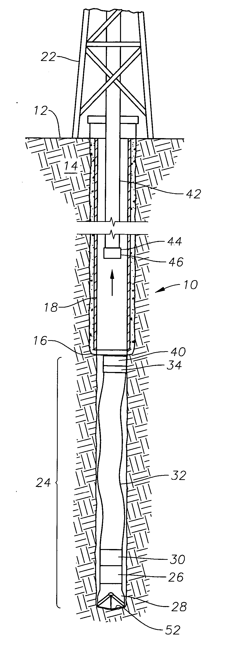
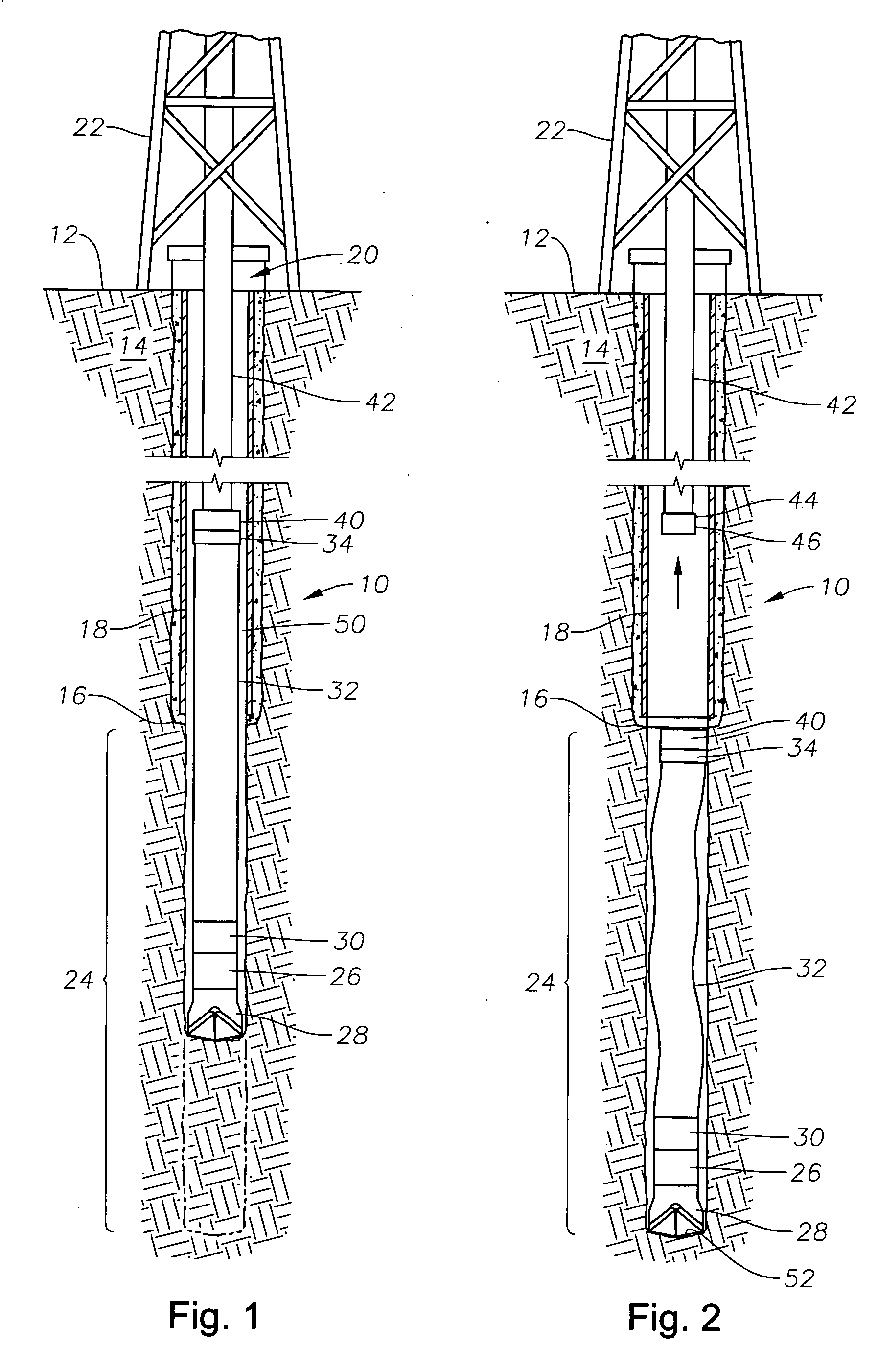
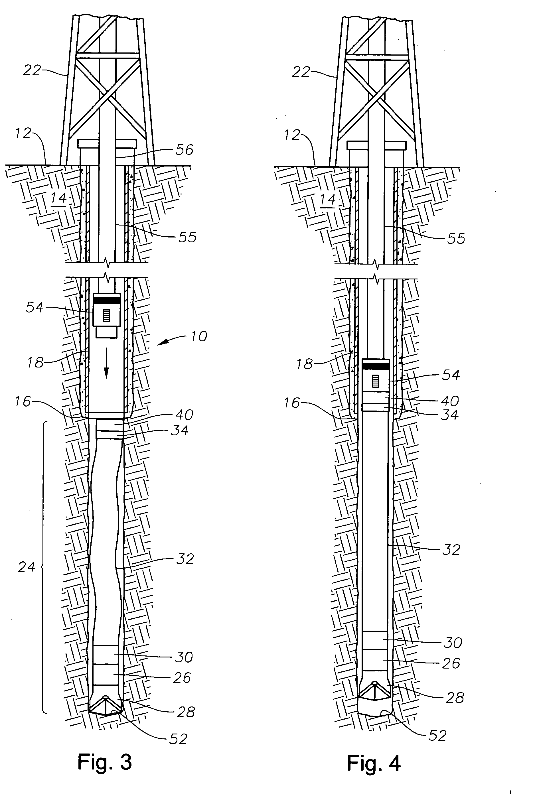
[0022]FIG. 1 depicts an exemplary wellbore 10 that has been drilled from the surface 12 through the earth 14 to an original depth 16. Metallic casing 18 has been cemented in the wellbore 10 from the surface 12 down near the original depth 16. A liner drilling system 20 has been inserted into the wellbore 10 from a drilling rig 22 at the surface 12. In FIG. 1, the liner drilling system 20 is drilling a deeper interval portion 24 of the wellbore 10. The liner drilling system 20 includes a bottom hole assembly 26 with a drill bit 28 thereupon. The bottom hole assembly 26 is attached by a landing collar 30 to a section of liner 32. The liner section 32 is of a length that approximates the length of the deeper interval portion 24 to be drilled. Secured to the upper end of the liner section 32 is a liner setting sleeve 34. The liner setting sleeve 34 is shown in greater detail in FIG. 7. It is noted that the liner setting sleeve 34 has a smooth external radial surface 36 and is affixed by...


PUM


Abstract

Methods and systems for conducting liner drilling and subsequent completion of the drilled section by cementing and anchoring the liner into place. The methods and systems prevent the liner from being cemented in in a bent or corkscrewed configuration. Additionally, there are no exterior components associated with the liner during drilling so as to allow relatively unrestricted return of drilling mud and cuttings.

Description

[0001] This application claims the priority of U.S. Provisional Patent Application Ser. No. 60 / 700,555 filed Jul. 19, 2005.BACKGROUND OF THE INVENTION [0002] 1. Field of the Invention [0003] The invention relates generally to devices and methods for conducting liner drilling and subsequent completion of the drilled section by securing the liner into place by anchoring and cementing. [0004] 2. Description of the Related Art [0005] In its basic form, a wellbore is drilled using a drill bit that is attached to a drill string fashioned of drill pipe. When the wellbore is drilled to an original desired depth, the drill string and bit are removed from the hole. Then steel casing is inserted into the borehole and cemented in place as a protective tubular sheath to prevent collapse of the borehole wall. The term “casing,” as used herein will refer to those protective sheaths that extend along a portion of the wellbore all the way to the surface. The well can then be drilled to deeper depths...

Claims


Application Information

Patent Timeline
IPC IPC(8): E21B7/00E21B23/01
CPCE21B7/20E21B33/04E21B43/10
Inventor MILLER, TROY A.GIVENS, GEORGEMYHRE, MORTEN
Owner BAKER HUGHES INC
Why Eureka
Try Eureka