Chair

Inactive Publication Date: 2007-05-17
KOKUYO CO LTD
View PDF57 Cites 78 Cited by
  • Summary
  • Abstract
  • Description
  • Claims
  • Application Information

AI Technical Summary

Benefits of technology

[0015] In addition, the backrest surface is structured by attaching an elastically deformable upholstery member on front surfaces of the plurality of frame elements, whereby it is possible to provide a soft sitting feeling having a reduced load by deforming while following various motions of the sitti

Problems solved by technology

However, the conventional chair does not take into consideration following the motion of the sitting person.
However, in the existing chair such as the example mentioned above, since both the right and left frame elements are rigidly coupled to each other via a lateral bridging member, and these frame elements are integrally mo

Method used


Image

  • Chair
  • Chair
  • Chair

Examples


Example

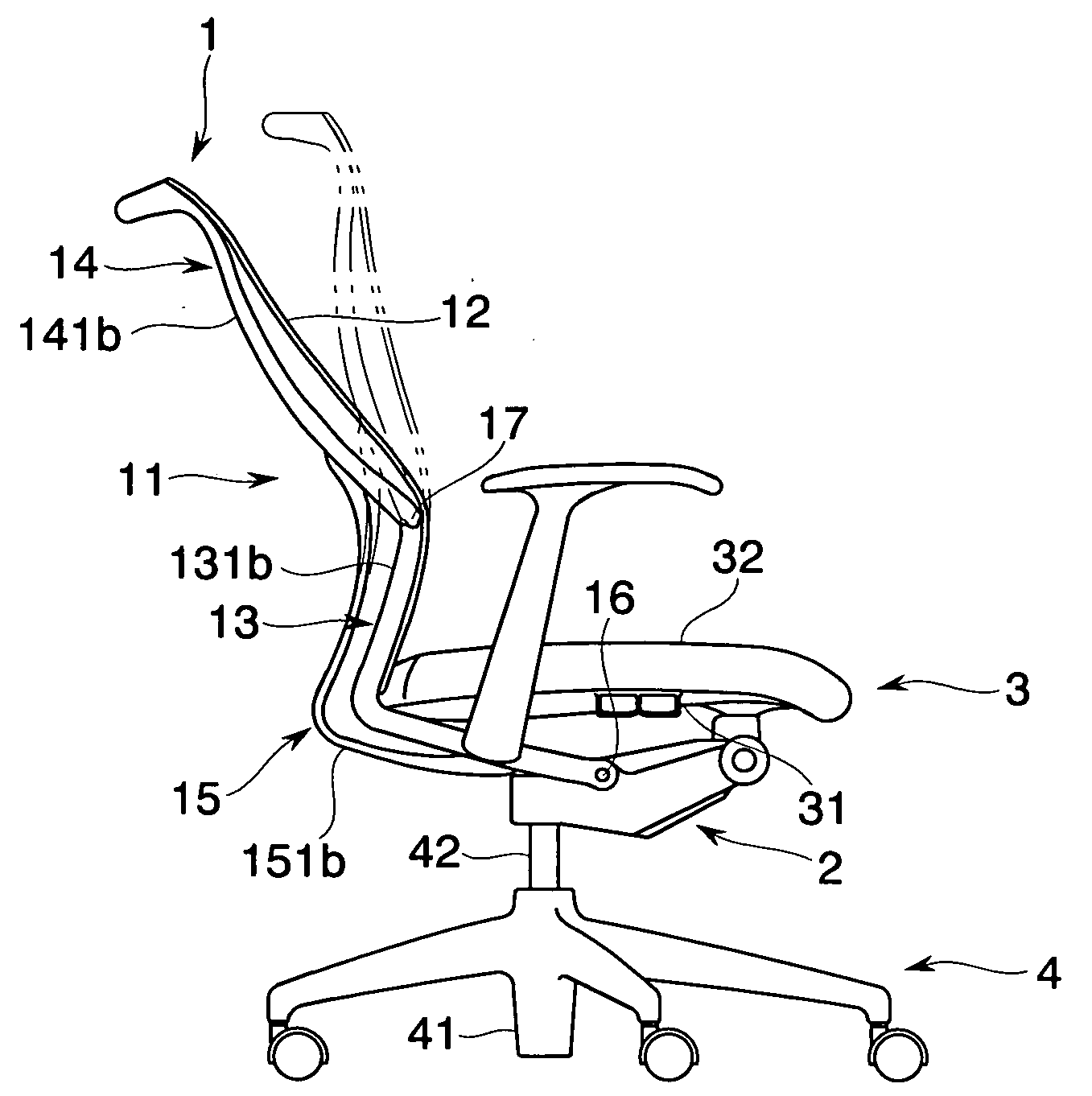
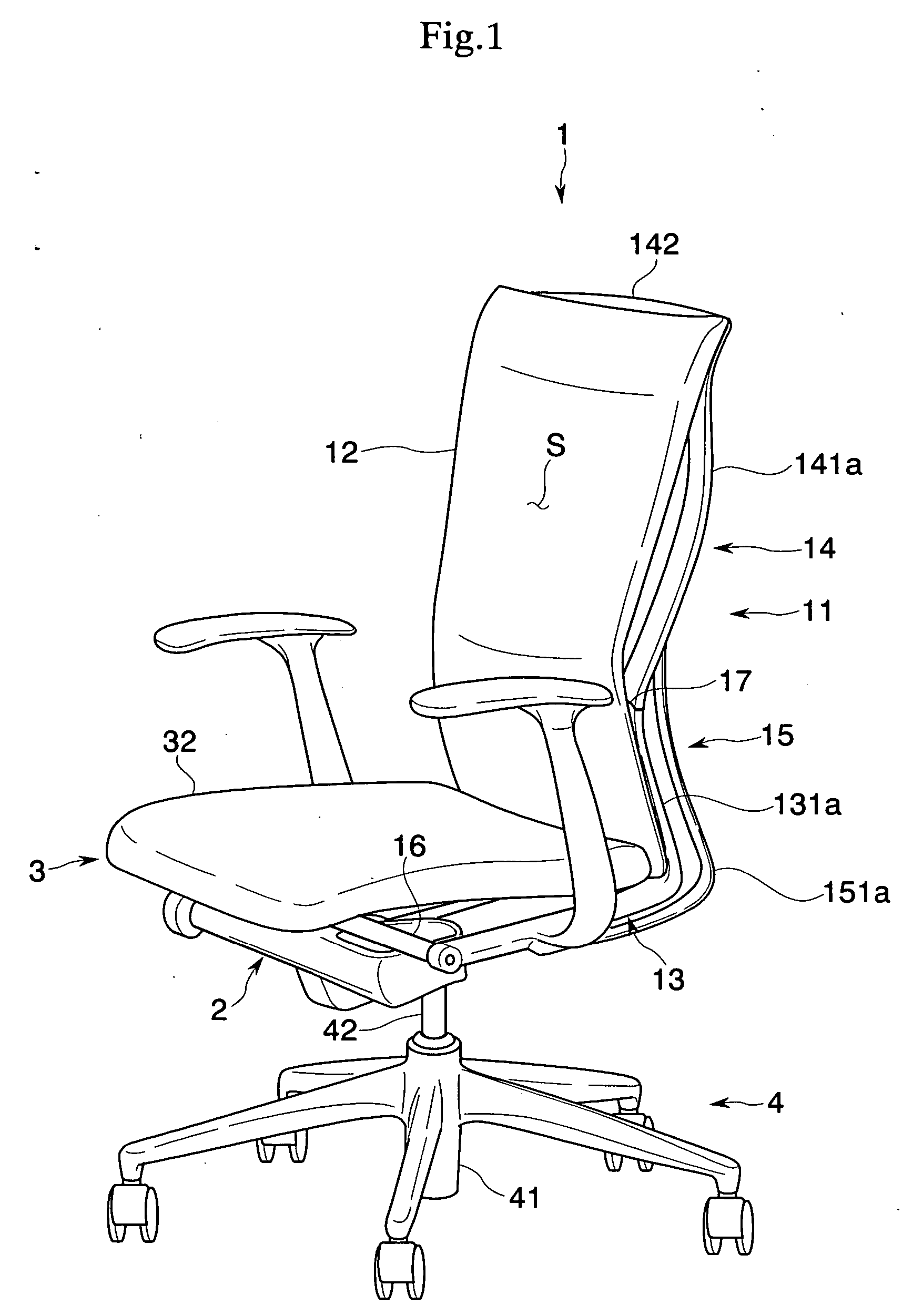
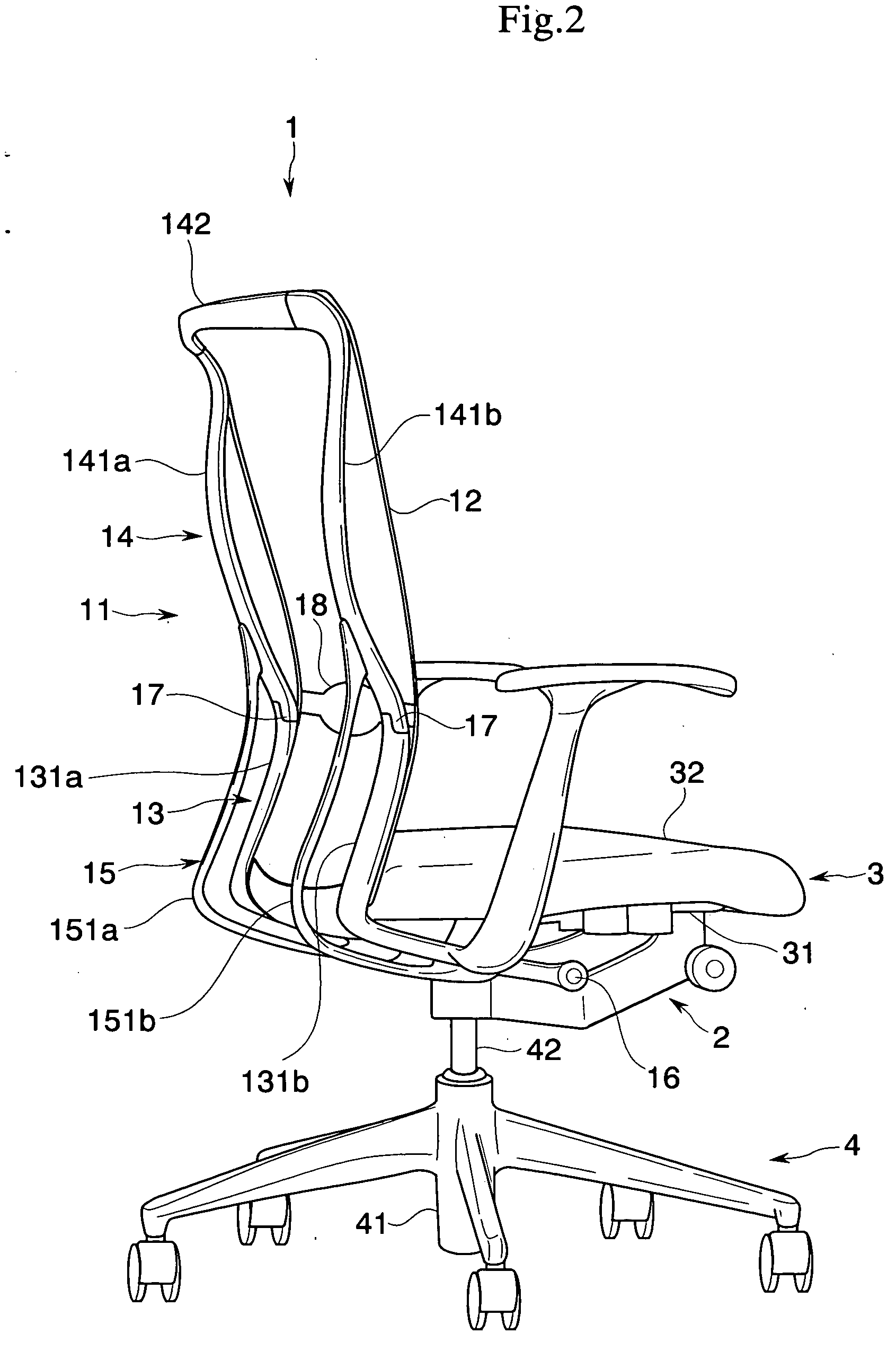
[0035] A description will be given below of an embodiment in accordance with the present invention with reference to the accompanying drawings. A chair in accordance with the present embodiment is provided with a leg body 4, a base body 2 supported by a leg body 4, a seat 3 arranged on the base body 2, and a backrest 1 pivoted to the base body 2 via a horizontal supporting shaft 16, as shown in FIGS. 1 to 5, and is structured such that the seat 3 and the backrest 1 are tilted in an interlocking manner, whereby a synchronized rocking motion can be executed.

[0036] In detail speaking, the leg body 4 is provided with a leg wing 41 to which a plurality of casters are installed, and a leg support pillar 42 uprising approximately vertically from a center of the leg blade 41, and the leg support pillar 42 can be protruded and contracted up and down based on expansion and contraction of a gas spring (not shown) interposed between the leg wing 41 and the leg support pillar 42.

[0037] The bas...


PUM


Abstract

The invention achieves a chair in which a shape of a backrest surface can be three-dimensionally changed while following a motion such as a sitting person looks around while sitting or the like. In a chair provided with a backrest in which an upper portion of a backrest surface is supported by a plurality of frame elements arranged so as to be spaced with each other in a width direction, the respective frame elements are independently movable backward and forward.

Description

BACKGROUND OF THE INVENTION [0001] 1. Field of the Invention [0002] The present invention relates to a chair in which a shape of a backrest surface can be three-dimensionally changed while following a motion of a body of a person sitting thereon. [0003] 2. Description of the Related Art [0004] There has been known a chair in which a backrest surface is structured by bridging an upholstery member between a pair of frame elements formed in both right and left sides. For example, Japanese Unexamined Patent Publication No. 2002-119375 and Japanese Unexamined Patent Publication No. 2002-119373 disclose a chair in which an upper portion of a backrest surface is supported by an upper frame element, a lower portion of the backrest surface is supported by a lower frame element, and the backrest surface can be formed in correspondence to a body type and a backbone shape of a sitting person through a rotating operation of the upper frame element and a rotating operation around a horizontal axi...

Claims


Application Information

Patent Timeline
IPC IPC(8): A47C3/00
CPCA47C1/03255A47C1/03261A47C7/40A47C7/445A47C31/023A47C7/4454
Inventor UEDA, NOBUYUKI
Owner KOKUYO CO LTD
Why Eureka
Try Eureka