Linear electrical machine for electric power generation or motive drive

a technology of electric power generation and motive drive, which is applied in the direction of dynamo-electric machines, electrical apparatus, magnetic circuits, etc., can solve the problems of noisy turbines, internal combustion engines and other power sources that are often too noisy for such applications, and achieve high permeability, high permeability, and high permeability.

Inactive Publication Date: 2007-05-17
TIAX LLC
View PDF99 Cites 51 Cited by
  • Summary
  • Abstract
  • Description
  • Claims
  • Application Information

AI Technical Summary

Benefits of technology

[0008] In yet another aspect of the invention, a reciprocating element including a low reluctance ferromagnetic frame supporting at least one magnet for reciprocation within a cavity formed in a machine core, there being a clearance gap between the machine core and the reciprocating element, the frame having a thicker section adjacent the gap, so as to desirably increase magnet flux linkage with an armature coil.
[0009] Numerous variations of the invention are contemplated. The ferromagnetic core elements may each include a core lamination stack including plural layers of a high permeability soft ferromagnetic sheet material. The support structure may further include a shell defining the plural spaces and further defining together with the core elements a cavity for receiving a coil, or the support structure may further include a plurality of generally wedge-shaped segments defining the plural spaces between faces of adjacent core elements and further defining together with the core elements a cavity for receiving a coil. The composite materia

Problems solved by technology

As a result, turbines, internal combustion engines and other pow

Method used


Image

  • Linear electrical machine for electric power generation or motive drive
  • Linear electrical machine for electric power generation or motive drive
  • Linear electrical machine for electric power generation or motive drive

Examples


Embodiment Construction

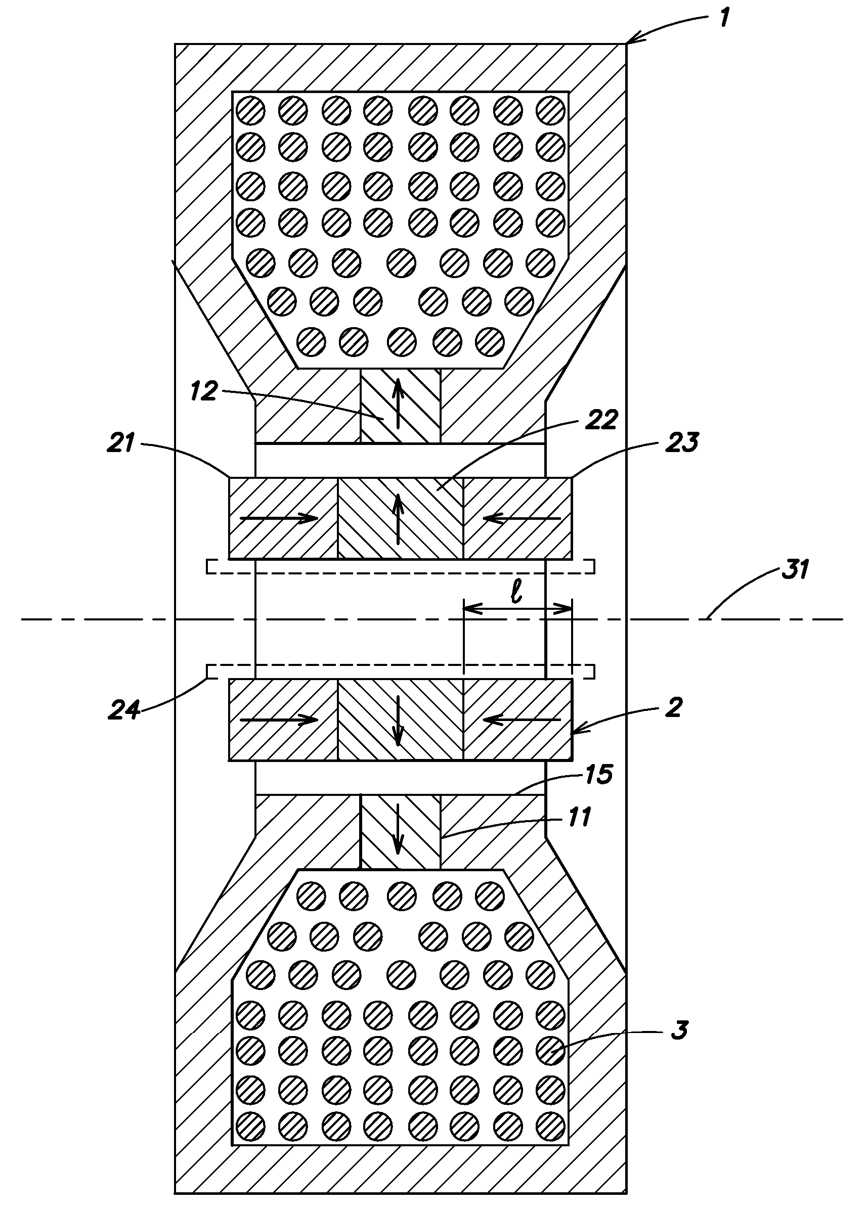
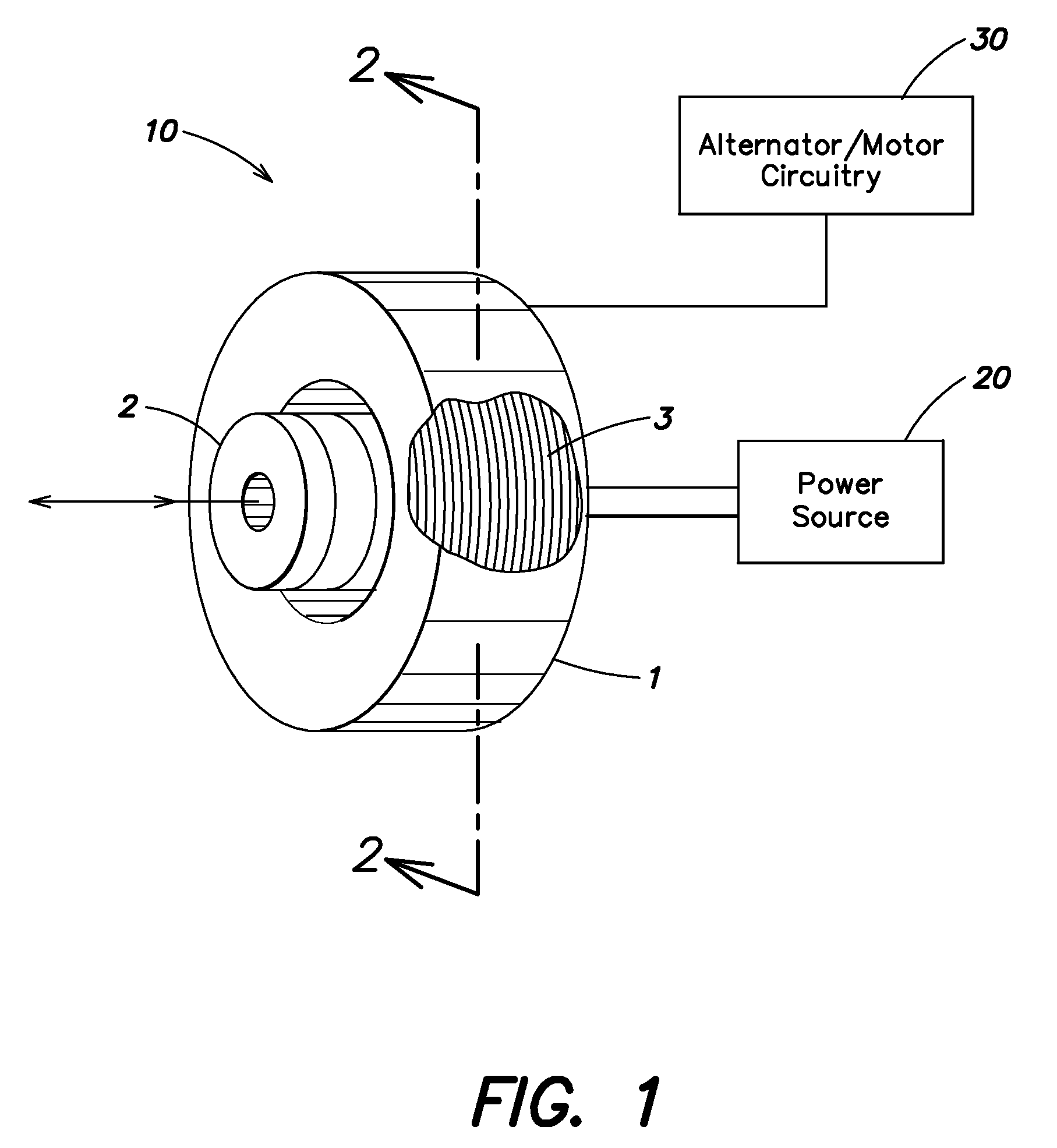
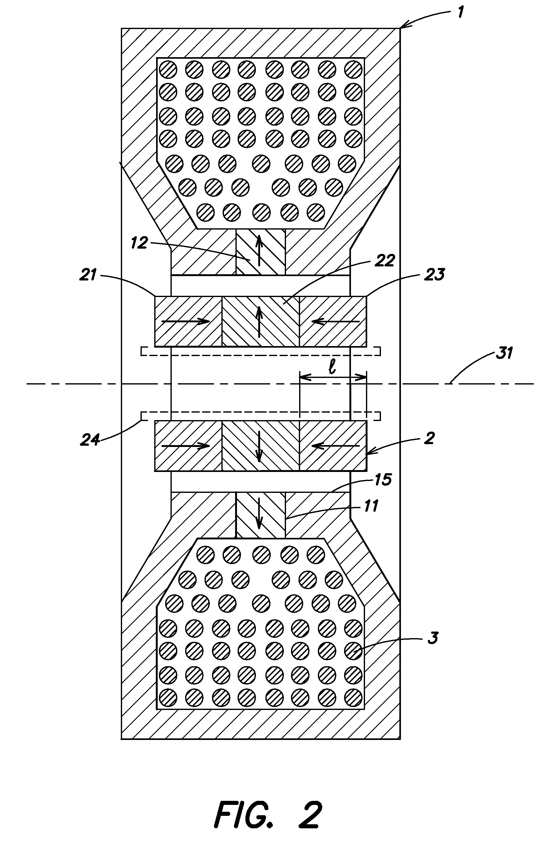
[0027] Aspects of the invention are not limited to the details of construction and arrangement of components set forth in the following description or illustrative embodiments. That is, aspects of the invention are capable of being practiced or of being carried out in various ways. For example, various illustrative embodiments are described below in connection with an electric power generator. However, aspects of the invention may be used in a linear motor (e.g., a device that can output a linear mechanical motion in response to an electric signal provided to the device). Also, the phraseology and terminology used herein is for the purpose of description and should not be regarded as limiting. The use of “including,”“comprising,” or “having,”“containing”, “involving”, and variations thereof herein, is meant to encompass the items listed thereafter and equivalents thereof as well as additional items.

[0028] In one aspect of the invention, a linear electrical machine includes a movabl...


PUM


Abstract

A linear electrical machine may function as an alternator or a motor. Three annular magnets may be provided that move relative to a core. The magnets may all have a different magnetic orientation. Two magnets may have a north pole oriented in a direction parallel to an axis along which the magnets move relative to the core. Another magnet may have a north pole oriented in a direction perpendicular to the axis. The core may include a plurality of ferromagnetic core elements; and a support structure composed of a composite material defining plural spaces, each for receiving one of the plurality of core elements. The core may further include a core shield disposed on the support structure substantially following a perimeter of the support structure defining an opening through which a reciprocating element can pass. Furthermore, the magnets may be supported in a reciprocating element having a low reluctance ferromagnetic frame there being a clearance gap between the machine core and the reciprocating element, the frame having a thicker section adjacent the gap, so as to desirably increase magnet flux linkage with an armature coil.

Description

RELATED APPLICATION [0001] The present application is a non-provisional application claiming the benefit under 35 U.S.C. § 119(e) of U.S. Provisional application Ser. No. 60 / 737,512, filed on Nov. 17, 2005. The present application is also related to U.S. patent application Ser. No. 10 / 612,723, filed on Jul. 2, 2003, and now issued as U.S. Pat. No. 6,914,351, having at least one common inventor, and incorporated herein by reference.BACKGROUND OF INVENTION [0002] 1. Field of Invention [0003] The invention relates to improvements to a linear electrical machine for electric power generation or motive drive. [0004] 2. Discussion of Related Art [0005] Quiet and efficient electric power generation can be important in a variety of applications. For example, boats and other spaces having power generation systems in close proximity to people have a need for quiet operation. As a result, turbines, internal combustion engines and other power sources are often far too noisy for use in such appli...

Claims


Application Information

Patent Timeline
IPC IPC(8): H02K41/00H02K35/00
CPCH02K1/145H02K33/16H02K35/02
Inventor CHERTOK, ALLAN
Owner TIAX LLC
Why Eureka
Try Eureka