

Motor driving method, program therefor, and motor driving apparatus
- Summary
- Abstract
- Description
- Claims
- Application Information
AI Technical Summary
Benefits of technology
Problems solved by technology
Method used
Image

Examples
first embodiment
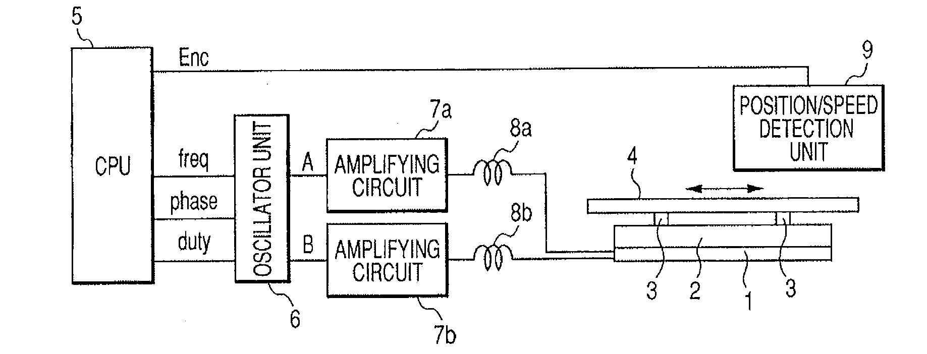
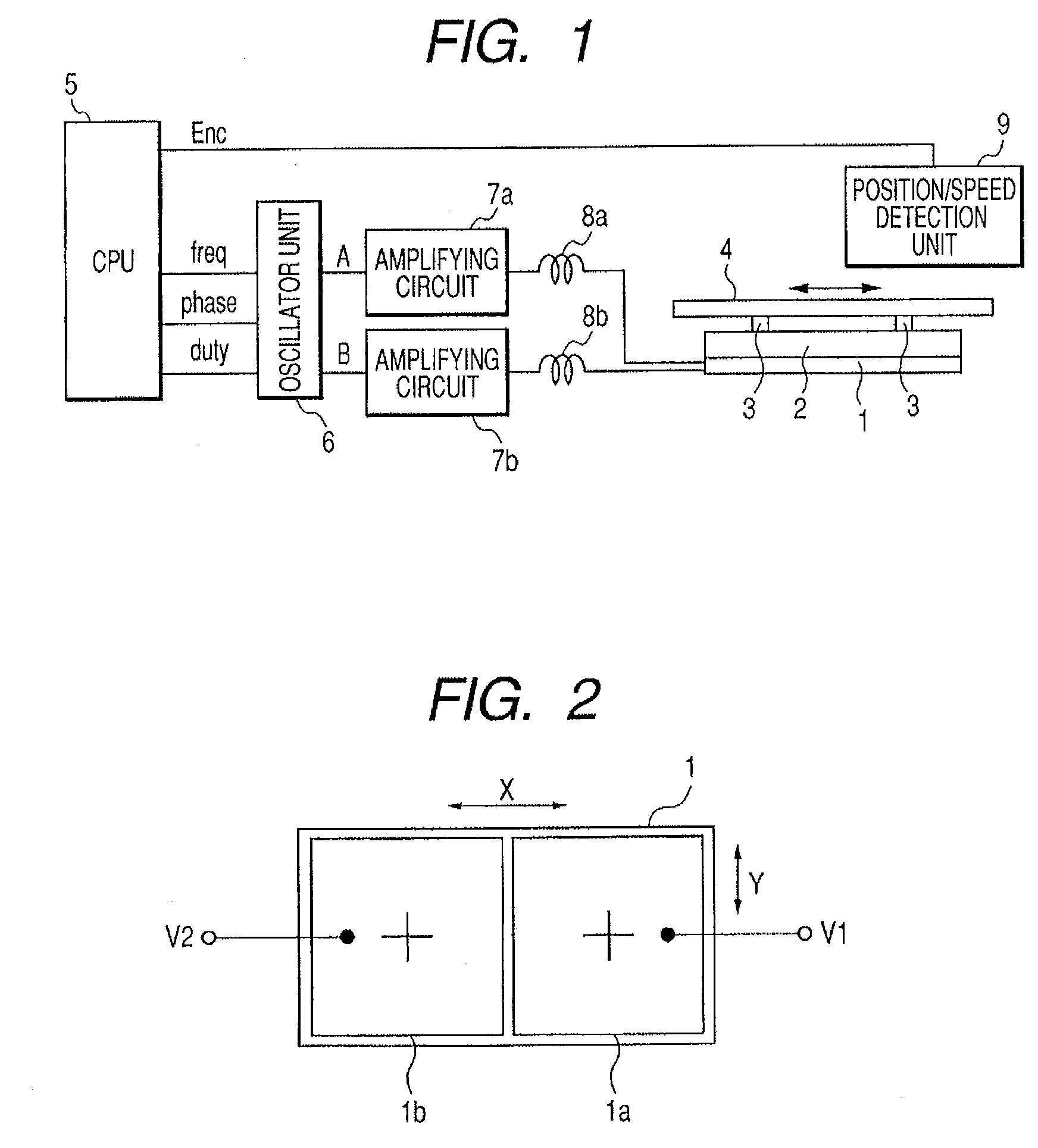
[0043]FIG. 1 is a block diagram showing a configuration of a vibration wave motor driving circuit as a motor driving apparatus according to a first embodiment of the present invention.
[0044] Referring to FIG. 1, a vibration wave motor is a compact nonelectromagnetic driving type motor which includes a piezoelectric element 1 and a vibration member 2 and moves a moving member (slider) 4 in an arrow direction. The vibration wave motor driving circuit includes a microcomputer (CPU) 5, an oscillator unit 6, amplifier circuits 7a and 7b, inductance elements 8a and 8b, and a position / speed detection unit 9.
[0045] In the vibration wave motor, the piezoelectric element 1 is an electro-mechanical energy conversion element for exciting high-frequency vibrations by applying two-phase driving voltages described below. The vibration member 2 is an elastic member having the piezoelectric element 1 bonded to its bottom surface and projection portions 3 arranged in its upper surface. In the vibra...
second embodiment
[0067] A second embodiment of the present invention is different from the first embodiment in that control described below is carried out in a vibration wave motor. Other features of this embodiment correspond to those of the first embodiment (described with reference to FIGS. 1 and 2), and thus description thereof will be omitted.
[0068]FIG. 7 is a diagram showing a relation between an AB phase difference and a driving speed of a moving member with respect to time in the vibration wave motor of this embodiment. In the embodiment, the CPU5 also performs a feedback control by using the speed information of the moving member 4, which is obtained by the position / speed detection unit 9, and also controls a phase difference between the driving frequencies f1 and f2 so that the driving member 4 drives to the predetermined position with the predetermined speed.
[0069] In FIG. 7, an abscissa indicates time, and an ordinate indicates an AB phase difference. According to the first embodiment,...
third embodiment
[0075] A third embodiment of the present invention is different from the first embodiment in that control described below is carried out in a vibration wave motor. Other features of this embodiment correspond to those of the first embodiment (described with reference to FIGS. 1 and 2), and thus description thereof will be omitted.
[0076]FIG. 8 is a diagram showing a relation between an AB phase difference and a driving speed of a moving member with respect to time in the vibration wave motor of this embodiment.
[0077] In FIG. 8, an abscissa indicates time, and an ordinate indicates an AB phase difference. A condition 1 indicated by the dotted arrow of FIG. 8 corresponds to a judging condition of whether “Xab>80°” is satisfied or not in step S15 of FIG. 9. A condition 2 indicated by the solid arrow of FIG. 8 corresponds to a judging condition of whether “Xab15 is satisfied or not FIG. 9. According to the first and second embodiments, the driving frequency is changed when the average ...
PUM
 Abstract
Description
Claims
Application Information