Wobble Information Recording Method, Information Recording Medium, and Recording and Reproduction Method and Apparatus Thereof

Inactive Publication Date: 2007-12-20
PANASONIC CORP
View PDF17 Cites 9 Cited by
  • Summary
  • Abstract
  • Description
  • Claims
  • Application Information

AI Technical Summary

Benefits of technology

[0012] forming a guide groove having wobble information wherein the wobble starts its first wobble deviation towards the inner side of the medium in the case where the selected recording system is a groove-recording system, or a guide groove having wobble information wherein the wobble starts its first wobble deviation towards the outer side of the medium in the case where the selected recording system is a land-recording system. This is particularly applicable to an optical disk on and from which information is recorded and reproduced with a light. This method makes it possible that the polarity of the wobble signals of the information recording medium of the groove-recording system is the same as that of the information recording medium of the land-recording system. According to this method, an information recording medium of groove-recording system, wherein a wobble starts its first wobble deviation towards the inner side of the medium in a guide groove having wobble information, and an information recording medium of land-recording system, wherein a wobble starts its first wobble deviation towards the outer side of the medium in a guide groove having wobble information can be obtained.
[0015] In these recording and reproduction method and apparatus, the default of the tracking polarity may be preferably one for a groove-recording system. Since many optical disks conventionally employ the groove-recording system, it may be considered that many unspecified optical disks also employ the groove-recording system. For this reason, the default of the tracking polarity is one for the groove-recording system and a detection time required for detecting an optical disk of the groove-recording system can be shorten, whereby the start time when the unspecified optical disk is loaded can be shortened.
[0016] This invention makes it possible to omit the time required for a recording and reproduction apparatus to study the wobble polarity of each optical disk irrespective whether its recording system is the groove-recording system or the land recording system. Further, the recording system of the information recording medium of the present invention can be easily judged by detecting whether or not the wobble information is obtained from the wobble signals when tracking is carried out under a predetermined polarity.

Problems solved by technology

For this reason, when it is desired that a single recording and reproduction apparatus accepts two types of optical disks, one being of the groove recording system, and the other being of the land-recording system, it is necessary to detect whether the portions to be used for recording is the groove portions or the land portions and to detect the wobble signal polarity for a loaded optical disk, which results in a problem that a longer time is required for start-up.

Method used


Image

  • Wobble Information Recording Method, Information Recording Medium, and Recording and Reproduction Method and Apparatus Thereof
  • Wobble Information Recording Method, Information Recording Medium, and Recording and Reproduction Method and Apparatus Thereof
  • Wobble Information Recording Method, Information Recording Medium, and Recording and Reproduction Method and Apparatus Thereof

Examples


first embodiment

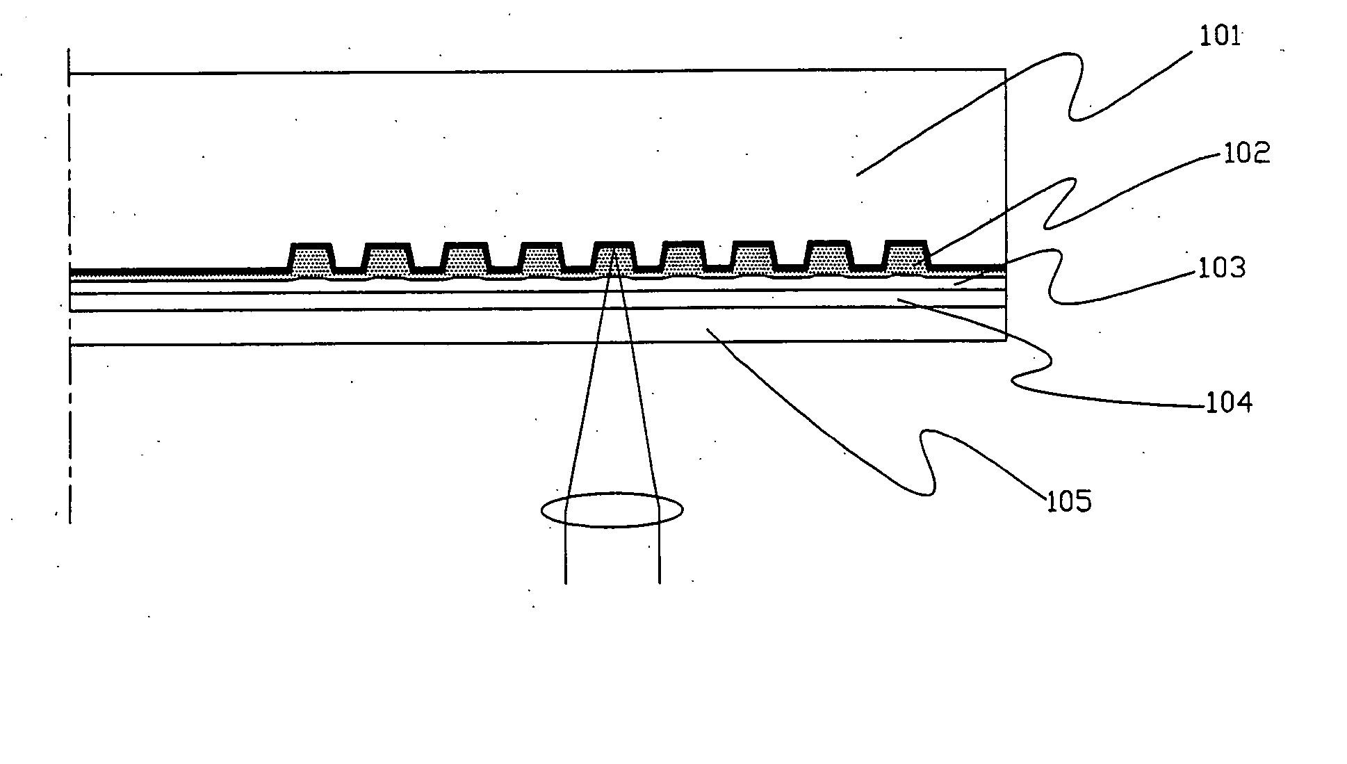
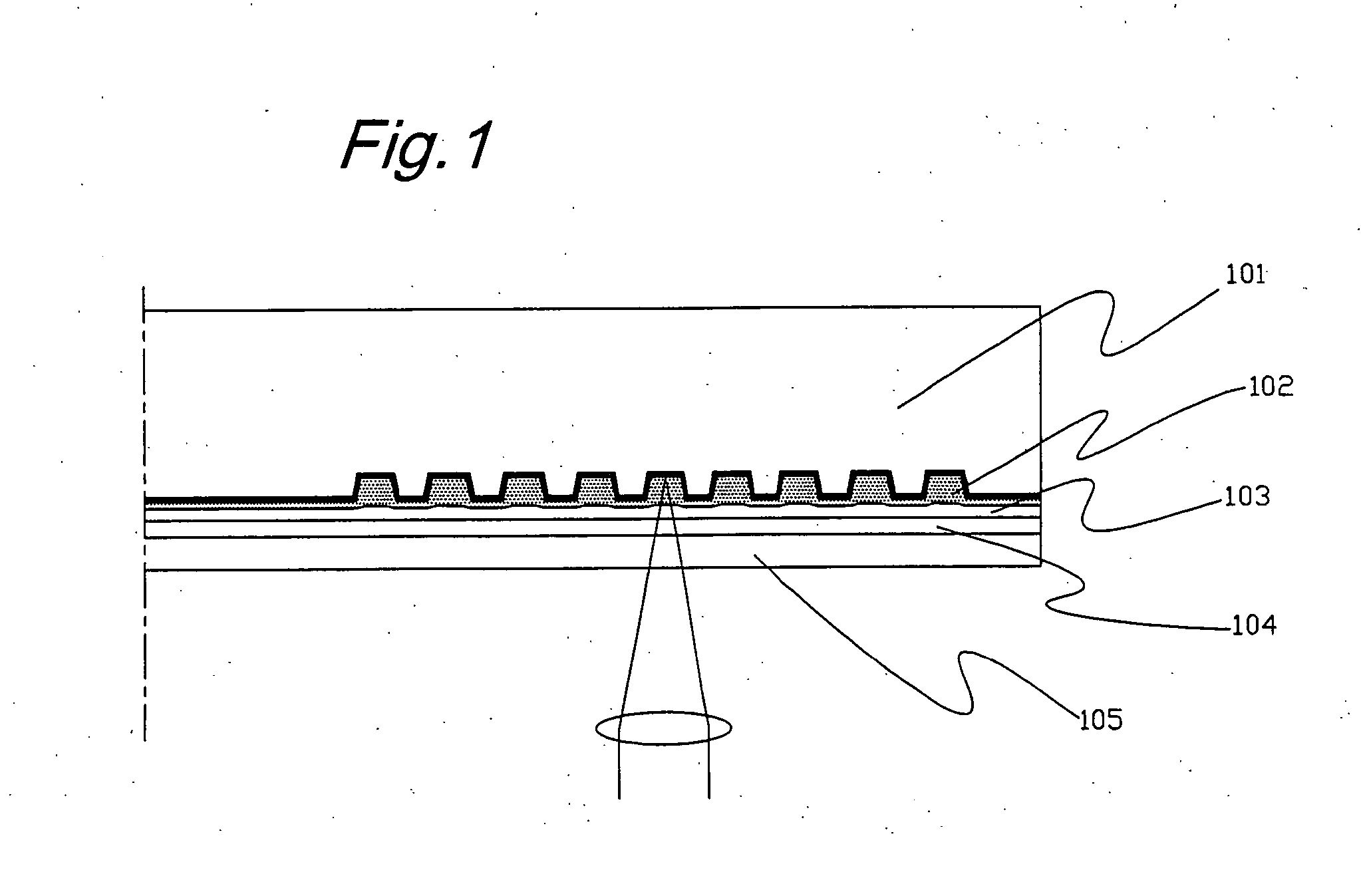
[0027]FIG. 1 shows a schematic view showing a construction of an optical disk according to the first embodiment of the present invention. The optical disk includes a substrate 101, a recording film 102 formed on a surface of the substrate 101, an overcoat layer 103 formed on a surface of the recording film 102 and a sheet 105 bonded to the overcoat layer 103 through an adhesive layer 104. The substrate 101 is a substrate (or plate) which is formed by injection molding and has a guide groove wherein wobble information is recorded on its surface where the recording film 102 is formed. The substrate 101 has a thickness of about 1.1 mm. The recording film 102 may be formed by, for example, a spin coat method using an organic dye. The overcoat layer 103 may be formed of a UV curable resin into a thickness of about 4 μm. The sheet 105 may be a polycarbonate sheet (PC sheet) having a thickness of about 80 μm, and it may be bonded to the overcoat layer 103 by the adhesive layer 104 of a UV ...

second embodiment

[0042]FIG. 5 is a schematic view showing a construction of an optical disk of a second embodiment. This disk has two recording films. A second recording film 502 which is located further from a laser light may be formed on a substrate 501 using an organic dye by a spin-coat method. The substrate 501 is produced in the same manner as in the first embodiment. Next, an intermediate layer 503 having a guide groove on its surface is stacked. The guide groove formed in the intermediate layer 503 is used to record information on and reproduce information from a first recording film 504 that is located near to the laser light and it also may be formed using a stamper which is produced with a master. The first recording film 504 whose main component may be a Te oxide film may be formed on a surface of the intermediate layer 503 by a sputtering method. A polycarbonate sheet (PC sheet) 506 having a thickness of about 65 μm is bonded to the surface of the second recording film 504 through a UV ...


PUM


Abstract

An optical disk and a method for identifying the optical disk are provided which make it possible to identify a recording system of the optical disk easily in a short time by a recording and reproduction apparatus when a groove-recording system and a land-recording system are both employed in one kind of optical disk, for, example, a BD-R. Specifically, the polarity upon reproducing the wobble information is made to be the same in both of the optical disk of groove-recording system and the optical disk of land-recording system. The recording system of the optical disk that shows the same wobble polarity irrespective of the recording system can be easily detected by finding a tracking polarity that can recognize the wobble information by changing the tracking polarity, whereby the start-up time of the recording and reproduction apparatus can be shortened.

Description

TECHNICAL FIELD [0001] The present invention is related to a method for recording wobble information of an information recording medium such as an optical disk so that a polarity of detected wobble information is the same irrespective of recording system, and an information recording medium wherein the wobble information is recorded according to the method. Further, the present invention is related to a method and apparatus for recording and reproducing information using the information recording medium. BACKGROUND OF THE INVENTION [0002] Conventionally, CD-R / RW or DVD-R / RW / RAM have been used as a write-once or an rewritable optical disk and recently demand for a DVD-R / RW / RAM has been increased since a DVD recorder has widely prevailed for recording TV broadcasts. A guide groove is provided in these optical disks and reference signals for synchronizing a linear velocity upon recording and reproducing and optional address information signals are recorded in these optical disks by “wo...

Claims


Application Information

Patent Timeline
IPC IPC(8): G11B7/007G11B7/00G11B7/005G11B7/2405G11B7/24082
CPCG11B7/0053G11B2007/0013G11B7/24082G11B7/007G11B7/0045G11B7/005G11B7/00
Inventor ABE, SHINYAISHIDA, TAKASHI
Owner PANASONIC CORP
Why Eureka
Try Eureka