Universal controller for automatic door systems

a universal controller and automatic door technology, applied in the direction of motor/generator/converter stopper, dynamo-electric converter control, instruments, etc., can solve the problems of serious physical harm, manual swinging doors can be hazardous to persons in close proximity to the doors, and the manual operation of such doors can be quite inconvenient, so as to reduce the time required

Active Publication Date: 2007-05-17
MOTIONACCESS
View PDF9 Cites 23 Cited by
  • Summary
  • Abstract
  • Description
  • Claims
  • Application Information

AI Technical Summary

Benefits of technology

[0018] A primary feature of this invention relates to providing a universal controller which is compatible and works with a plurality of different automatic door manufactured systems thus reducing the time required to return an inoperative automatic door system to proper working order.
[0019] Another feature of the present

Problems solved by technology

Manually operating such doors, however, can be quite inconvenient especially when there is a large volume of pedestrian traffic passing into and out of a large store, or when persons needing access are laden with bulky items which need to set aside to allow for manual operation of the doors, followed by the extra effort of relifting and balancing of the items to be transported to or from the store.
Manually operated swinging doors can also be hazardous to persons in close proximity to the doors, when passers through open the doors suddenly as they enter or exit the store.
As will be appreciated, manually operated swinging doors can cause serious physical harm, to others.
Every day the store having such automatically controlled door s

Method used


Image

  • Universal controller for automatic door systems
  • Universal controller for automatic door systems
  • Universal controller for automatic door systems

Examples


Embodiment Construction

[0029] While the present invention is susceptible of embodiment in multiple forms, there is shown in the drawings and will hereinafter be described a preferred embodiment of the invention, with the understanding the present disclosure sets forth an exemplification of the invention which is not intended to limit the invention to the specific embodiment illustrated and described.

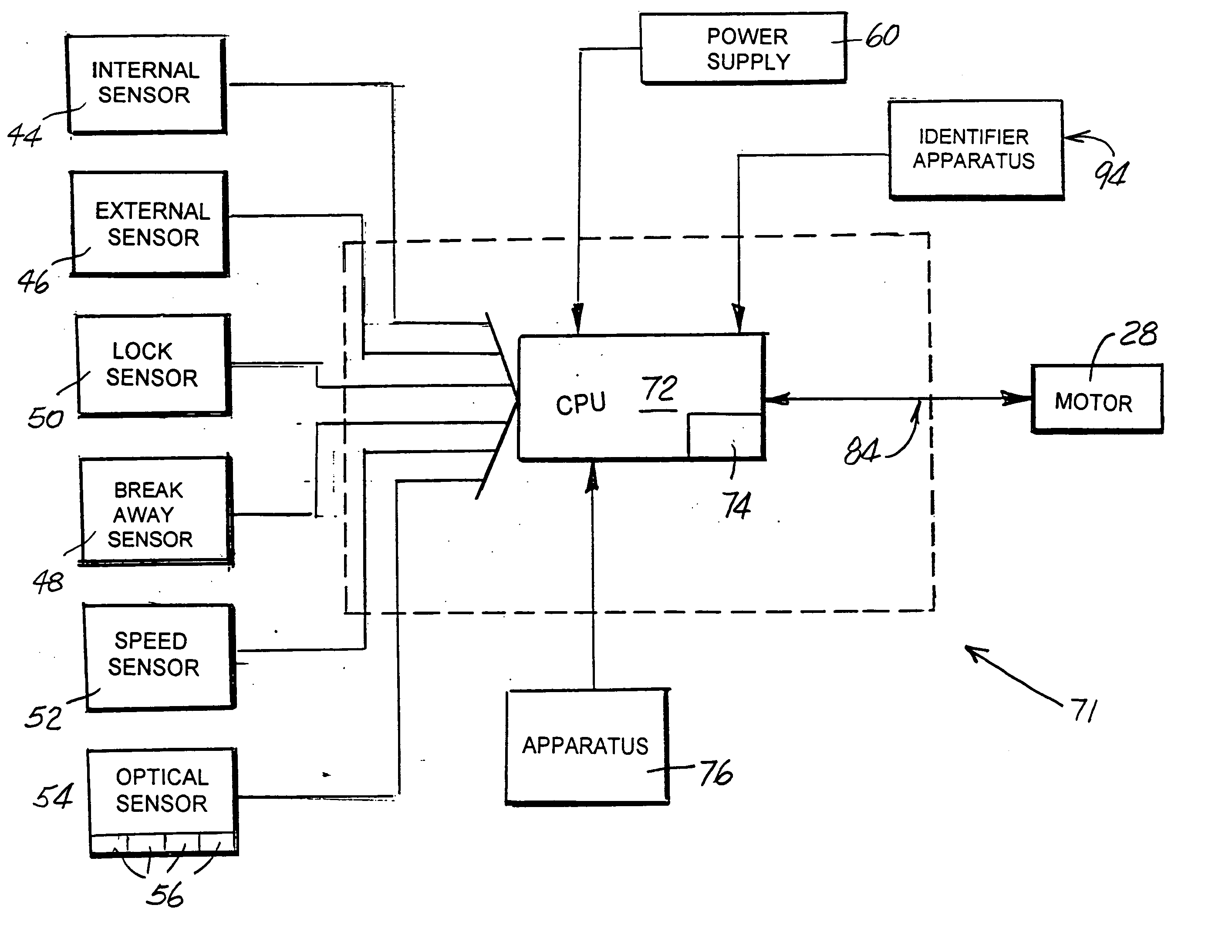
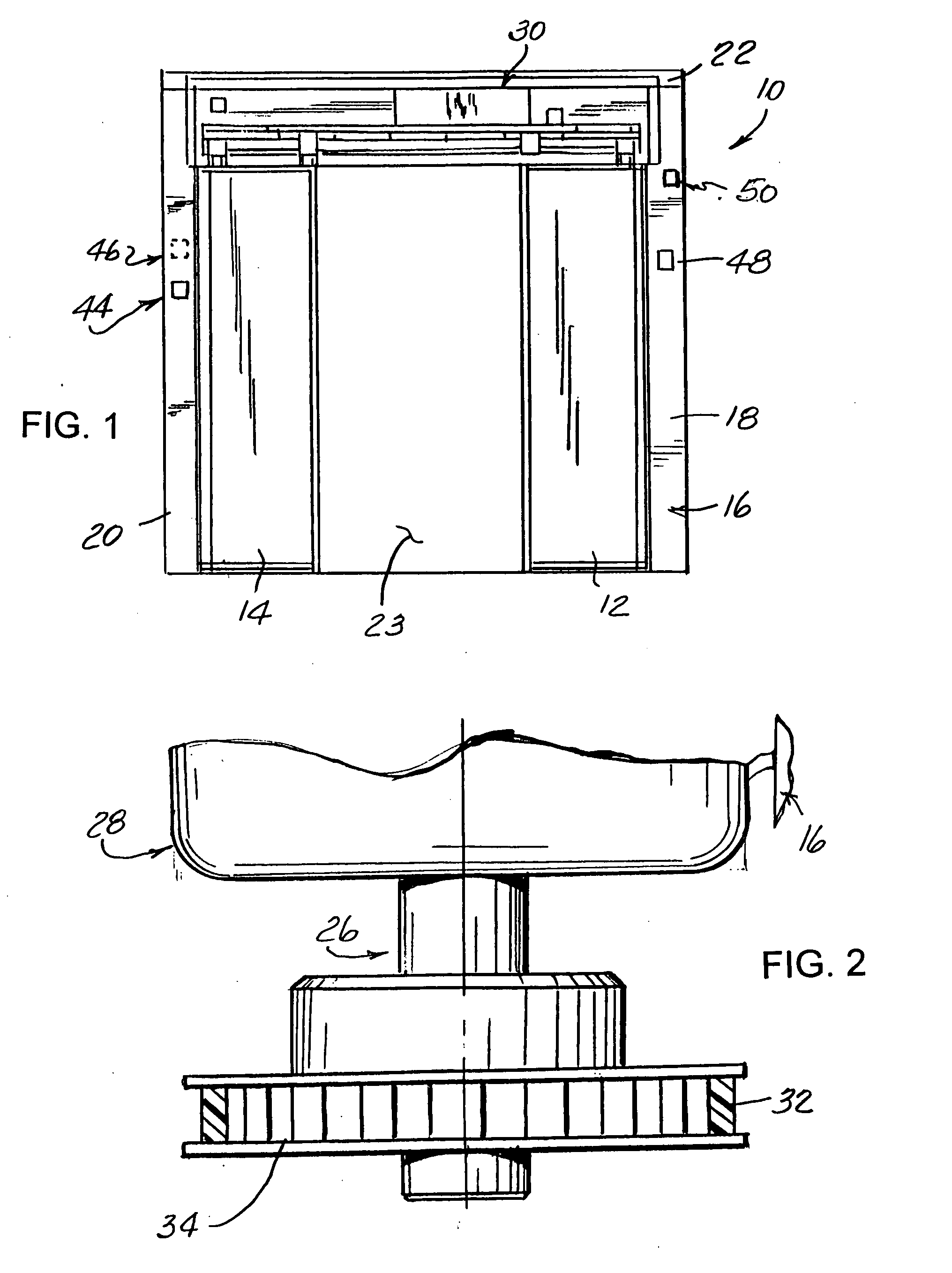
[0030] Referring now to the drawings wherein like reference indicate like parts throughout the several views, there is shown in FIG. 1 a front view of one form of automatic door system, generally identified by reference numeral 10. The automatic door system 10, illustrated for exemplary purposes in FIG. 1, includes a bi-parting door arrangement including a first door 12 and a second door 14, shown in the open position in FIG. 1. Each door 12, 14 is mounted for sliding movement along a predetermined path of travel. Surrounding the doors 12, 14 is a suitable door frame 16. In the illustrated embodiment, the doo...


PUM


Abstract

A universal controller for an automatic door system including a door carried on a frame for movement along a predetermined path of movement between open and closed positions. The universal controller includes a housing for mounting the controller in a stationary position relative to the door frame and an assembly including a processor carried by the housing for processing data operatively received from a plurality of sensors and relating to the operation of the movable door. The processor is configured to generate operational values which are transmitted to and control a drive motor used to move the door between the open and closed positions. The assembly further includes an arrangement for adjusting the operational values generated by the processor and transmitted to the drive motor. A modular harness connects the controller to the drive motor and to the sensors. An apparatus operably coupled to the modular harness identifies the particular drive motor and sensors used in combination with the automatic door system. A method for automatically controlling operation of an automatic door system having at least one door movable between open and closed positions in response to operation of an output drive of a bi-directional drive motor is also provided.

Description

FIELD OF THE INVENTION [0001] The present invention generally relates to automatically operated door systems and, more particularly, to a universal controller and a method for operating automatic door systems. BACKGROUND OF THE INVENTION [0002] In the past, ingress an egress to stores and the like have often been through swing-type doors that need to be manually opened and closed. Manually operating such doors, however, can be quite inconvenient especially when there is a large volume of pedestrian traffic passing into and out of a large store, or when persons needing access are laden with bulky items which need to set aside to allow for manual operation of the doors, followed by the extra effort of relifting and balancing of the items to be transported to or from the store. Manually operated swinging doors can also be hazardous to persons in close proximity to the doors, when passers through open the doors suddenly as they enter or exit the store. As will be appreciated, manually o...

Claims


Application Information

Patent Timeline
IPC IPC(8): H02P3/00H02P1/00
CPCE05F17/004E05Y2400/40E05Y2400/82E05Y2800/11E05Y2800/21E05F15/73E05Y2900/132E05F15/43E05F15/643E05F15/70E05F15/00
Inventor VALENCIA, MICHAEL A.MADDEN, JOSEPH P.VALENCIA, GILBERT F.OAKLEY, ROBERT L.
Owner MOTIONACCESS
Why Eureka
Try Eureka