
Image processing apparatus

a technology of image processing and apparatus, applied in the field of image processing apparatus, can solve the problems of switching between two types of contour extraction, excessively emphasized edges, and defects especially at the boundary

Inactive Publication Date: 2007-05-17
OLYMPUS CORP
View PDF12 Cites 6 Cited by
  • Summary
  • Abstract
  • Description
  • Claims
  • Application Information

AI Technical Summary

Benefits of technology

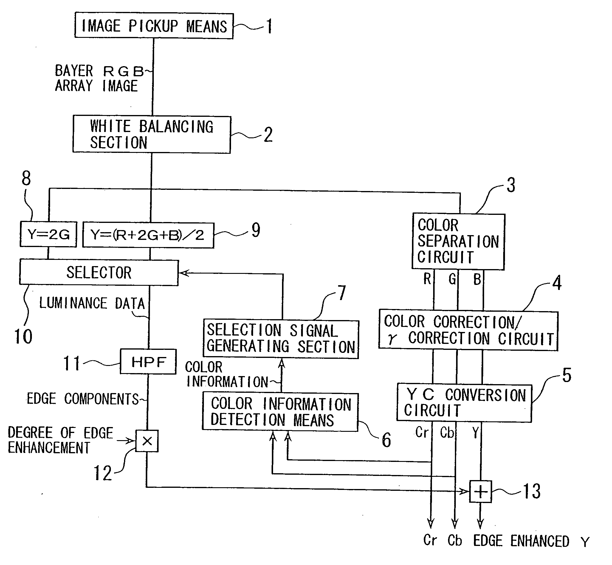
[0011] By such construction, an output is provided on the basis of color information obtained at the color information detection means by switching between output of the first luminance data generation means for finding luminance data from G signal and output of the second luminance data generation means for finding luminance data from all color signals of the image signals. Hence edge enhancing components can be extracted on the basis of an optimal luminance data corresponding to the color information, an edge enhancement processing is possible with a favorable S / N and with less edge noise in high saturation regions and low saturation regions. The above object is thereby achieved.
[0045] By such construction, an output is provided as switched between the setting signal of the first mixing ratio setting means for setting the mixing ratio of the mixed luminance data generation means based on color information and the setting signal of the second mixing ratio setting means for setting the mixing ratio of the mixed luminance data generation means based on edge information on the basis of the joint information of image for joint boundary portions of image and on the basis of the determination signal of the image region determination means for those other than the joint boundary portions of image. Hence, in joining a plurality of images, the edge enhancement processing can be performed corresponding to the characteristic of the object smoothly at favorable S / N and without unnaturalness at the joint portions. The above object is thereby achieved.

Problems solved by technology

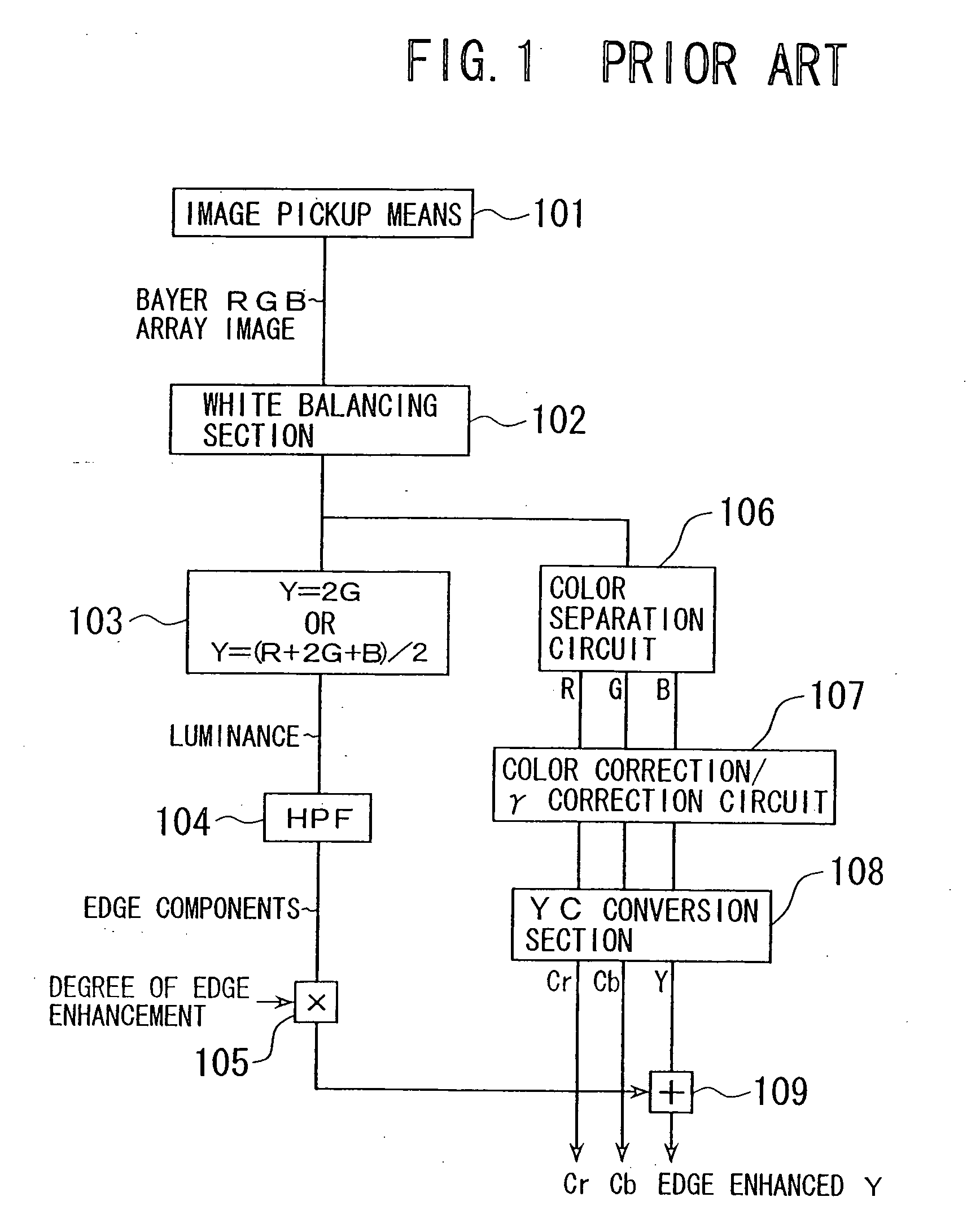
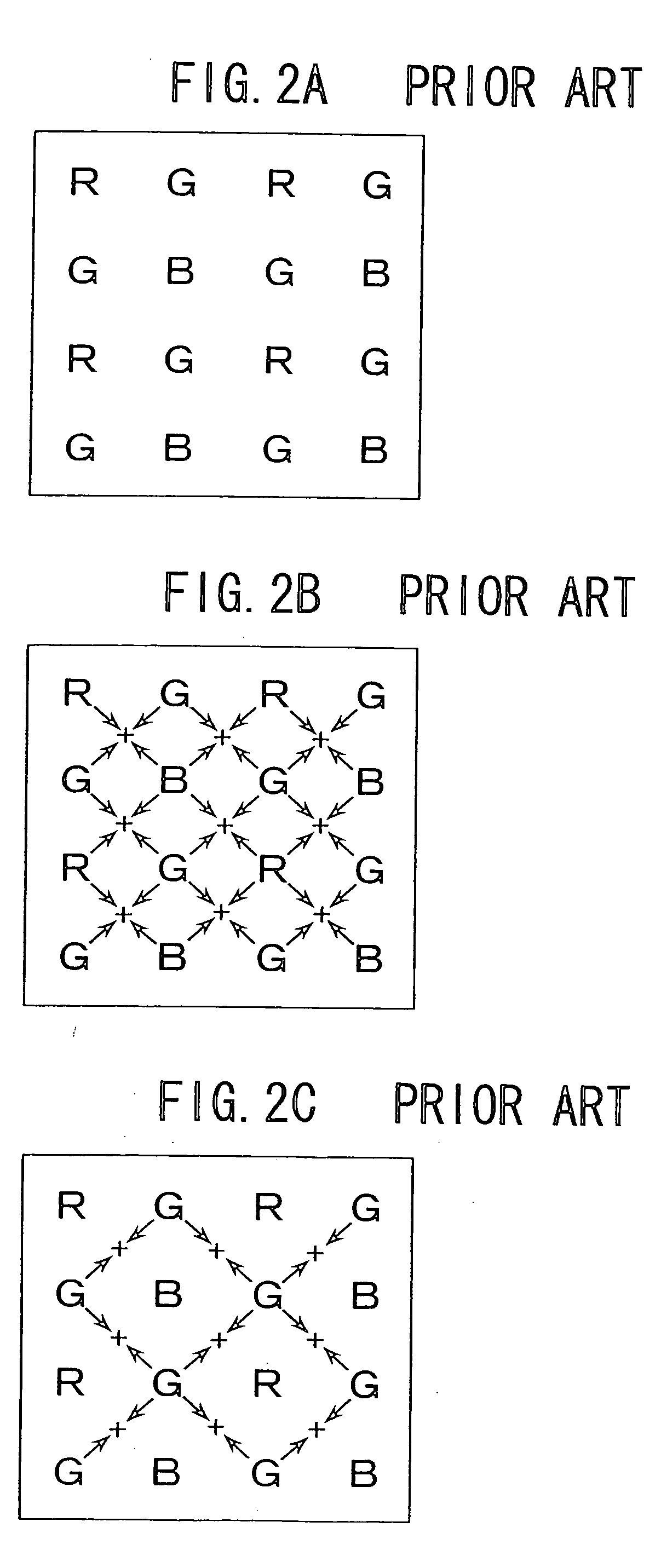
Since, however, the signals of R, B, which contain not much genuine luminance information, are used as luminance signal when 4 pixels of RGB are used, excessively emphasized edges are generated and defects occur especially at the portion of boundary between two highly saturated colors.
Thus the problem is that there are respective merits and demerits as described above of the technique for generating luminance signal by using only G signals in the image to extract edge components and the technique for generating luminance signal by using all the color signals of RGB in the image to extract edge components.
Further, the contour enhancement technique as disclosed in the above Japanese patent laid open application Hei-9-261513 has a problem that, if Bayer RGB array is used as the color filter array of image pickup device, the mere switching between the two types of contour extracting methods according to saturation alone may, depending on the colors of image, fall short of suitable processing due to lack of information.
Furthermore, there is a problem of complicated construction in the NAM mode, since it is necessary to perform addition by respectively selecting one emphasized most in the direction of black and one emphasized most in the direction white out of the contour enhancement signals.

Method used


Image

  • Image processing apparatus
  • Image processing apparatus
  • Image processing apparatus

Examples


first embodiment

[0071] Some embodiments will now be described. FIG. 3 is a block diagram showing the image processing apparatus according to the present invention. Included in FIG. 3 are: image pickup means 1 for outputting image signals of Bayer RGB array; a white balancing section 2; a color separation circuit 3 for separating the image signals into RGB signals by pixel as a unit; a color-correction / γ-correction circuit 4; YC conversion circuit 5; color information detection means 6 for detecting color information based on Cr, Cb color signals outputted from YC conversion circuit 5; a selection signal generating section 7 for generating a selection signal based on color information signal outputted from the color information detection means 6: a first luminance data generating section 8 for generating luminance data for use in edge enhancement based on G signals of the image signals processed of white balancing at the white balancing section 2; a second luminance data generating section 9 for gen...

seventh embodiment

[0115] the invention will now be described. In general, methods for forming a large one piece of image by joining a plurality of images are used for example in making a panoramic picture. If different edge (contour) enhancement processing techniques are used at the joint boundary portions when making a panoramic picture by means of such joining of a plurality of images, unnaturalness due to the difference in processing remains to occur at such boundary portions.

[0116] The seventh embodiment is constructed so that, when the present invention is applied to image processing apparatus for making a large one frame of image such as the above panoramic picture by joining a plurality of images, the same luminance data generating technique is used at the boundary of joining of images adjoining each other so as not to leave unnaturalness in edge enhancement processing at the joint boundary portions as described above.

[0117]FIG. 20 is a block diagram showing a seventh embodiment wherein the l...

third embodiment

[0123] It should be noted that, also in this embodiment, 2G or (R+2G+B) / 2 can be used as the luminance signal in finding edges from an image at the edge detection means 31 in a similar manner as in the Further, in switching the luminance data generation technique based on edge information and joint information, the switching is performed for every pixel based on joint information for the joint boundary portions of image and the switching is performed based on edge information for those other than the joint boundary portions of image.

[0124] An application of the fourth embodiment to an image processing apparatus having a joining processing section is shown as a tenth embodiment in FIG. 23. In this embodiment, mixed luminance data is generated by mixing the luminance data generated from G signals and the luminance data generated from all color signals with continuously changing the mixing ratio based on edge information and joint information. It is thereby possible in performing join...


PUM


Abstract

An image processing apparatus includes: an image pickup section for converting an object light into image signals of Bayer RGB array; a color information detecting section for obtaining color information of the object from the image signals obtained by the image pickup section; a first luminance data generating section for finding luminance data for use in edge enhancement processing based on G signals of the image signals obtained by the image pickup section; a second luminance data generating section for finding luminance data for use in edge enhancement processing based on all color signals of the image signals; a selector for providing an output by switching between outputs of the first and second luminance data generating section; and a selection signal generating section for generating selection signal for controlling the switching of the selector based on color information obtained at the color information detecting section. The image processing apparatus is thereby achieved as capable of edge enhancement processing at favorable S / N and with less occurrence of edge noise in high saturation regions and low saturation regions.

Description

[0001] This application is a divisional of application Ser. No. 10 / 947,250, filed Sep. 30, 2004 which is a division of application Ser. No. 09 / 695,420, filed Oct. 25, 2000, now U.S. Pat. No. 6,816,193.BACKGROUND OF THE INVENTION [0002] The present invention relates to image processing apparatus, and more particularly to an image processing apparatus having a digital image processing section including enhancement of edges in image to be displayed. When an image is processed for edge enhancement, a technique is generally used to extract edge components within the image so as to add the extracted edge components to the original image. In such case, the edge components to be added are obtained by extracting high-frequency components of luminance signals of the image. In image pickup devices using RGB primary-color filter, the techniques for generating luminance signal to extract such high-frequency components include: (1) technique for generating luminance signal by using only G (green)...

Claims


Application Information

Patent Timeline
Patent Type & Authority Applications(United States)
IPC IPC(8): H04N9/73H04N5/208G06T1/00G06T5/20H04N1/409H04N1/46H04N1/60H04N5/14H04N9/07H04N9/64H04N9/68
CPCH04N5/142H04N9/045H04N9/646H04N25/447H04N25/134
Inventor KOHASHI, ATSUSHISAKURAI, JUNZO
Owner OLYMPUS CORP
Learn More