Side emitting near field lens

Active Publication Date: 2007-05-17
VARROC LIGHTING SYST
View PDF99 Cites 50 Cited by
  • Summary
  • Abstract
  • Description
  • Claims
  • Application Information

AI Technical Summary

Benefits of technology

[0004] One embodiment of the present invention provides a near field lens which reduces the size of the near field lens. Generally, the near field lens includes a main body of light transmitting material and a pocket formed in the main body for receiving light from the light source. The main body defines an outer longitudinally facing surface an

Problems solved by technology

However, manufacturing larger lenses poses complex molding issues and takes hi

Method used


Image

  • Side emitting near field lens
  • Side emitting near field lens
  • Side emitting near field lens

Examples


Embodiment Construction

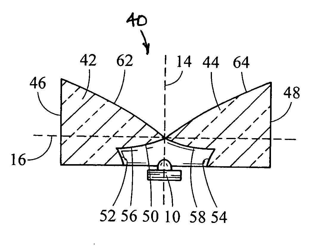
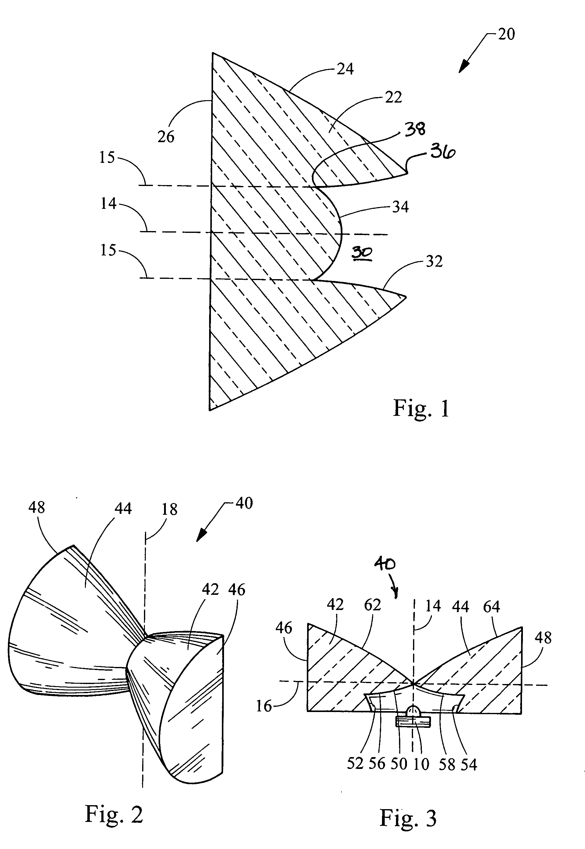
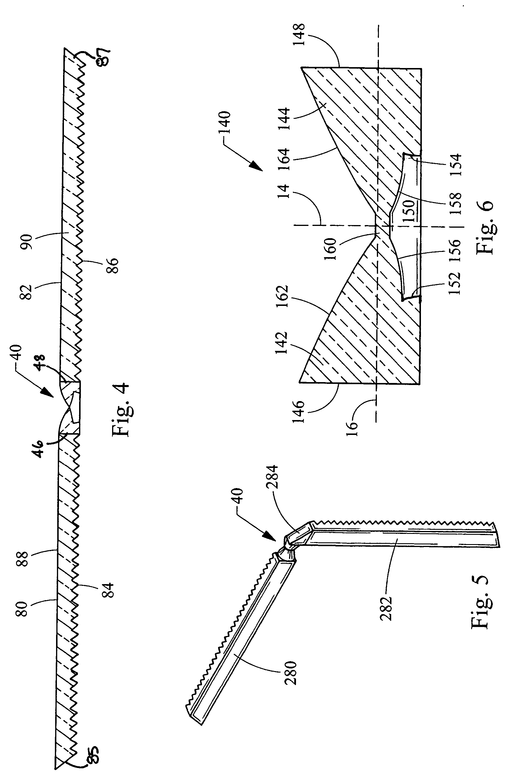
[0021] Turning now to the figures, FIG. 1 depicts an axial near field lens 20 having a reduced thickness as measured in the longitudinal direction along axis 14, the details of which may be found in co-pending U.S. patent application Ser. No. 11 / 252,008 (Attorney Docket No. 10541-2290) filed Oct. 17, 2005, and which is incorporated herein by reference in its entitety. The near field lens 20 will be used as a reference in describing the construction of the near field lenses 40, 140, 240, 340 described below in accordance with the teachings of the present invention. As shown in FIG. 1, the NFL 20 includes a main body 22 defining a longitudinal axis 14. The NFL 20 collects, collimates and redirects light downstream along the axis 14. The main body 22 generally includes an outer laterally facing surface 24 which redirects light towards an outer longitudinally facing surface 26 through which light is emitted. A pocket 30 is formed in the main body 22 for receiving light from a light sour...


PUM


Abstract

A near field lens for an automotive light assembly which has a reduced thickness. Generally, the near field lens includes a main body of light transmitting material. A pocket is formed in the main body for receiving light from a light source. The pocket is defined by an inner radially facing surface and an inner axially facing surface. The inner radially facing surface is structured to reduce the thickness of the lens.

Description

FIELD OF THE INVENTION [0001] The present invention relates generally to automotive light modules having near field lenses collecting and directing light from sources such as light emitting diodes. BACKGROUND OF THE INVENTION [0002] Light emitting diodes (LED's) are fast becoming the preferable light source for automotive lighting applications, as they consume less power but provide light output which is acceptable for such applications. Near field lenses (NFL's) are used to collect as well as to collimate the light from a LED source, and generally provide high light collection efficiency (typically 70-90%), but the output beam size for a given source depends on the size of the lens. The larger the lens size (i.e. the larger the starting focal length of the lens), the smaller of the output beam size and the higher the peak intensity. However, manufacturing larger lenses poses complex molding issues and takes higher molding cycle time, thus requiring expensive molding tools and proce...

Claims


Application Information

Patent Timeline
IPC IPC(8): F21V5/00H01L33/00H01L33/58
CPCF21S48/1233F21S48/1241F21S48/1329F21S48/215F21S48/2212F21S48/2225F21S48/236F21V5/04F21V7/0091F21Y2101/02F21Y2115/10F21S41/28F21S41/24F21S41/322F21S43/14F21S43/26F21S43/235F21S43/315
Inventor CHINNIAH, JEYACHANDRABOSEFALLAHI, AMIR P.ERION, JEFFREY ALLENSAYERS, EDWIN MITCHELLJONES, THOMAS LEE
Owner VARROC LIGHTING SYST
Why Eureka
Try Eureka