Door with structural components configured to radiate acoustic energy

a technology of structural components and doors, applied in the field of doors, can solve the problem of relative large volume of loudspeakers, and achieve the effect of providing sound reliably and comprehensively

Inactive Publication Date: 2007-05-17
HARMAN AUDIO ELECTRONICS SYST
View PDF22 Cites 9 Cited by
  • Summary
  • Abstract
  • Description
  • Claims
  • Application Information

AI Technical Summary

Benefits of technology

[0007] A door leaf includes a stiff, light structural part that maintains fed-in vibrational energy and, by flexural waves, propagates this energy in at least one active surface perpendicular to its thickness to distribute resonance mode vibration components over at least one surface, which has specified, preferred locations or sites within it for transducer devices, which are affixed on the structural part at one of the locations or sites to set the structural part into vibration and to allow it to resonate, thus creating an acoustic radiator that delivers an acoustic output signal when it vibrates in resonance, the front and / or the rear cover panel of the door leaf being part of the stiff, light structural component. The transducer(s) is / are situated between the cover panels. This arrangement provides a door with a loudspeaker function, which needs no extra volume compared to an ordinary door, and which is able to provide sound reliably and comprehensively to one or more rooms, which adjoin this door acting as a loudspeaker. Advantageously, additional loudspeakers or loudspeaker boxes are not required in a room that receives sound by this door with loudspeakers.

Problems solved by technology

One disadvantage of this motor vehicle door is that a relatively large loudspeaker must be built into the door to radiate sound.

Method used


Image

  • Door with structural components configured to radiate acoustic energy
  • Door with structural components configured to radiate acoustic energy
  • Door with structural components configured to radiate acoustic energy

Examples


Embodiment Construction

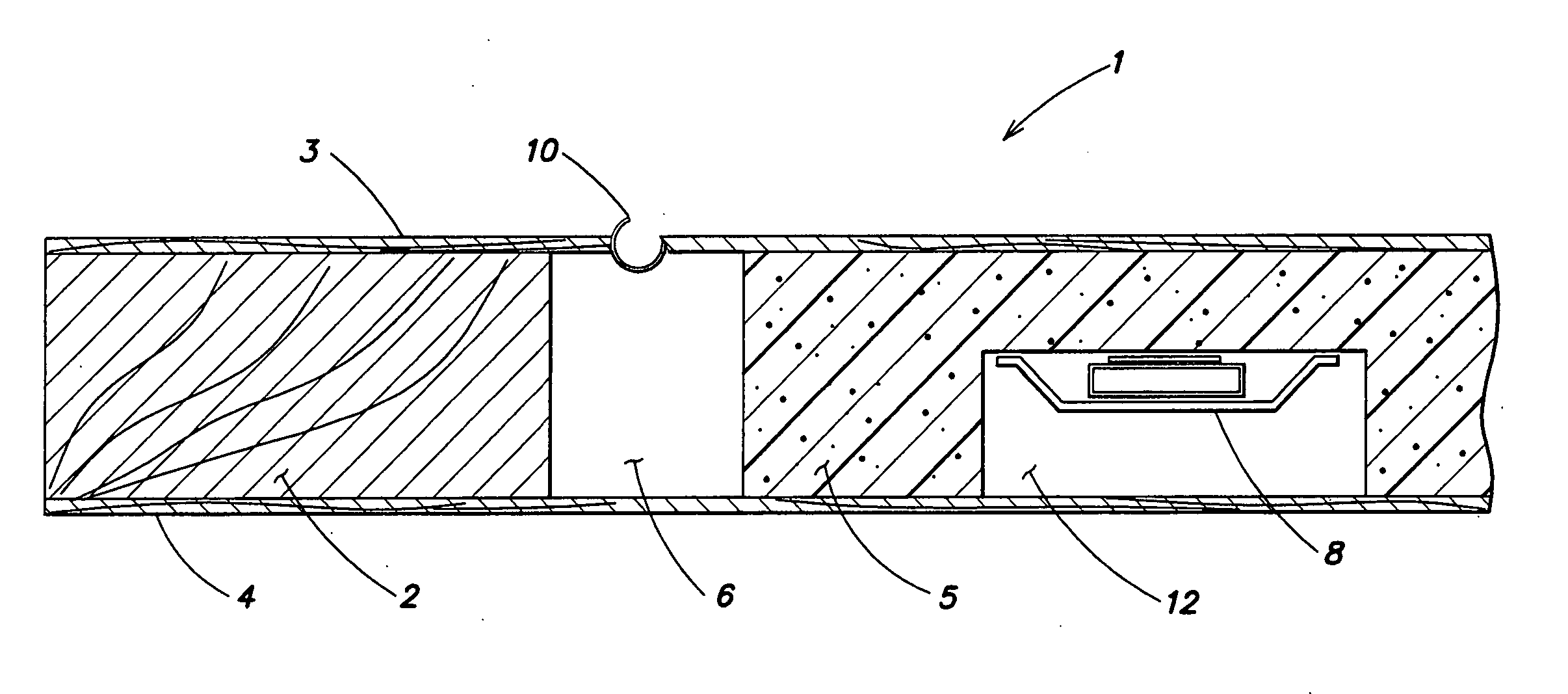
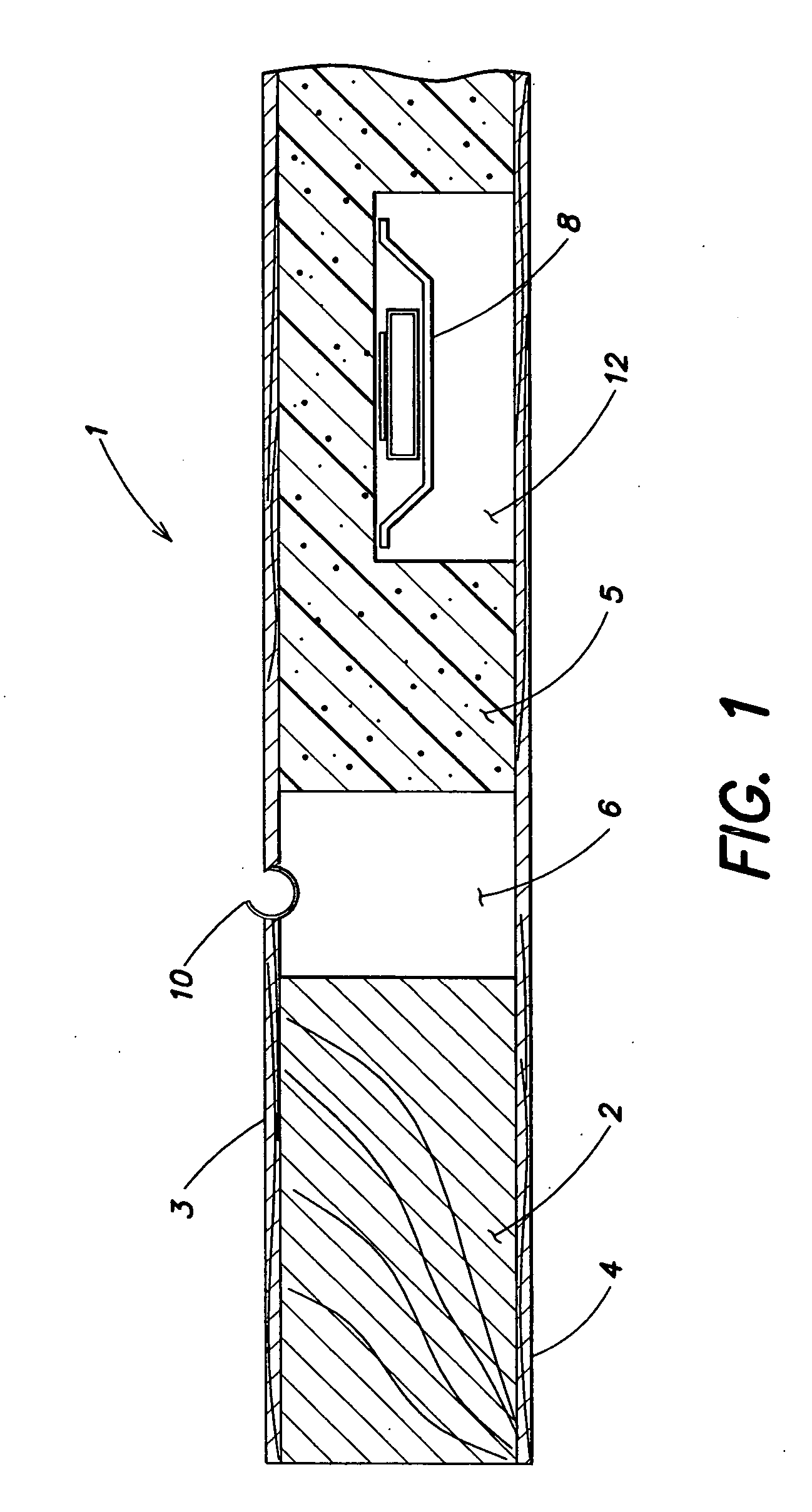
[0025]FIG. 1 illustrates, partially in section, a segment of a door leaf 1 that acts as a loudspeaker. The door leaf 1 has a frame 2 with front and rear cover panels 3, 4, respectively. The frame 2 and the front and rear cover panels 3, 4 bound an interior space 6 of the door leaf 1. An acoustic sandwich core 5 of highly resistant foam is disposed within the interior space 6 and extends from the front cover panel 3 to the rear cover panel 4. The front cover panel 3, the acoustic sandwich core 5, and the rear cover panel 4 form a stiff, light structural part, which may be excited to flexural vibrations in such a way that it acts as a multimodal resonance radiator and delivers an acoustic output signal when it vibrates in resonance.

[0026] The acoustic sandwich core 5 has a recess 12, which is occupied by a transducer 8. When excited by an electric acoustic signal, the transducer excites the acoustic sandwich core 5, together with the adjoining cover panels 3 and 4, to flexural vibrat...


PUM


Abstract

A door leaf includes a stiff, light structural part that maintains fed-in vibrational energy and, by flexural waves, propagates this energy in at least one active surface perpendicular to its thickness to distribute resonance mode vibration components over at least one surface, which has specified, preferred locations or sites within it for transducer devices, which are affixed on the structural part at one of the locations or sites to set the structural part into vibration and to allow it to resonate, thus creating an acoustic radiator that delivers an acoustic output signal when it vibrates in resonance, the front and/or the rear cover panel of the door leaf being part of the stiff, light structural component. The transducer(s) is/are situated between the cover panels. This arrangement provides a door with a loudspeaker function, which needs no extra volume compared to an ordinary door, and which is able to provide sound reliably and comprehensively to one or more rooms, which adjoin this door acting as a loudspeaker. Advantageously, additional loudspeakers or loudspeaker boxes are not required in a room that receives sound by this door with loudspeakers.

Description

PRIORITY INFORMATION [0001] This application is a continuation of co-pending Ser. No. 09 / 665,894 filed Sep. 20, 2000.BACKGROUND OF THE INVENTION [0002] The present invention relates to the field of loudspeakers, and in particular to a door that acts as a radiant acoustical structure. [0003] U.S. Pat. No. 3,247,925 discloses a flat panel loudspeaker, which has a multimodal resonance radiator element formed by two films between which is arranged a core consisting of high resistance foam or a core with a honeycomb structure. This radiator is driven by electrodynamic transducers that excite the radiator to multimodal resonance in accordance with a fed-in electrical audio signal to yield a corresponding acoustic audio signal. [0004] U.S. Pat. No. 3,247,925 describes a woofer having an electromagnet disposed on the floor of its cubical housing. A flat, first diaphragm fastened on the housing like an intermediate ceiling is seated on this electromagnet. The housing ceiling is formed by a s...

Claims


Application Information

Patent Timeline
Patent Type & Authority Applications(United States)
IPC IPC(8): H04R25/00H04R1/02
CPCH04R5/023
Inventor BACHMANN, WOLFGANGKRUMP, GERHARDREGL, HANS-JUERGENZIGANKI, ANDREAS
Owner HARMAN AUDIO ELECTRONICS SYST
Why Eureka
Try Eureka