Centrifugal fans and impellers thereof

Active Publication Date: 2007-05-17
DELTA ELECTRONICS INC
6 Cites 8 Cited by

AI-Extracted Technical Summary

Problems solved by technology

Thus, the blades are easily deformed or damaged during operation of the centrifugal fan.
The mold, however, is easily broken during formation of the blades.
Accordingly, the summation of the blades of the impeller of the centrifugal fan cannot be increased, such that wind pressure and wind volume provided by t...

Benefits of technology

[0016] In the aforementioned centrifugal fan or impeller, as the impeller can comprise blades with two or more than two types,...

Abstract

A centrifugal fan. A hub covers a driving device. An impeller surrounds the hub and includes a first blade set and a second blade set. The first blade set surrounds the hub and includes a first combining portion, a second combining portion, and a plurality of first blades. The first and second combining portions are respectively connected to the first blades. The second blade set includes a third combining portion, a fourth combining portion, and a plurality of second blades. The third and fourth combining portions are respectively connected to the second blades. The first blade set is assembled with the second blade set by assembling the first combining portion with the third combining portion and assembling the second combining portion with the fourth combining portion.

Application Domain

Technology Topic

Image

  • Centrifugal fans and impellers thereof
  • Centrifugal fans and impellers thereof
  • Centrifugal fans and impellers thereof

Examples

  • Experimental program(1)

Example

[0020] The following description is of the best-contemplated mode of carrying out the invention. This description is made for the purpose of illustrating the general principles of the invention and should not be taken in a limiting sense. The scope of the invention is best determined by reference to the appended claims.
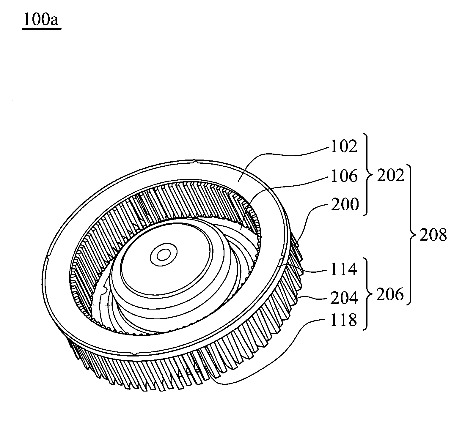
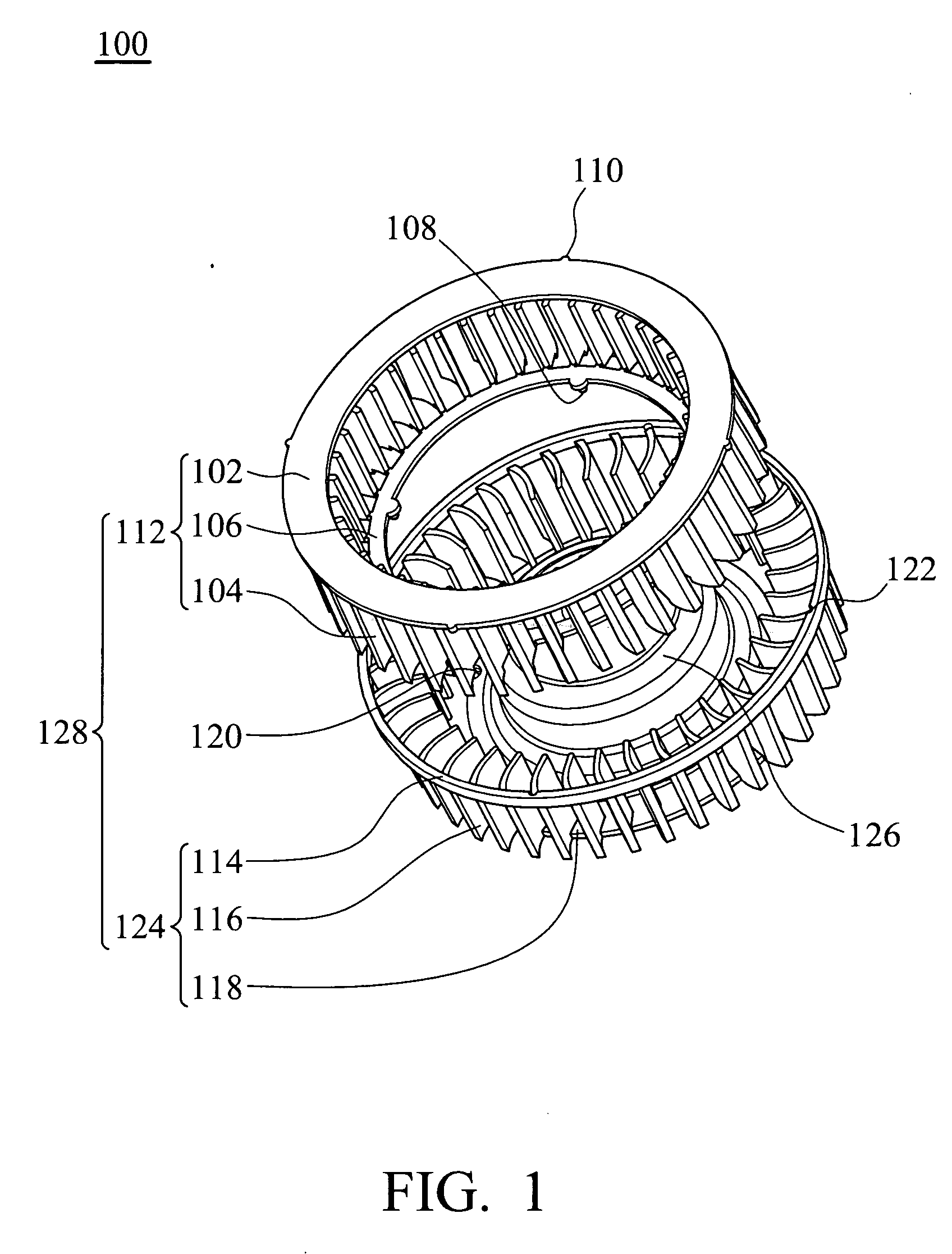
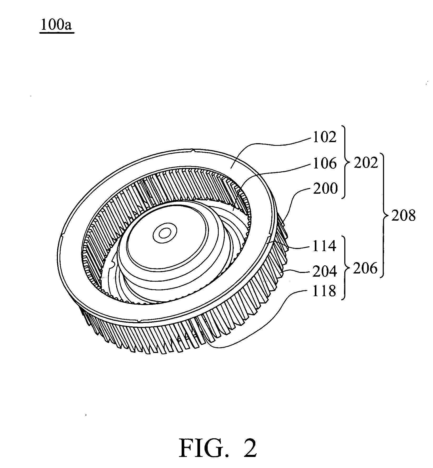
[0021]FIG. 1 is a schematic exploded view of a centrifugal fan 100 of an embodiment of the invention. The centrifugal fan 100 comprises a hub 126 and an impeller 128. The hub 126 covers a driving device (not shown) and the driving device drives the fan to rotate. The hub 126 may be cylindrical or tubular.
[0022] The impeller 128 surrounds the hub 126 and comprises a first blade set 124 and at least one second blade set 112. The first blade set 124 surrounds the hub 126 and comprises a first combining portion 114, a second combining portion 118, and a plurality of first blades 116. The first combining portion 114 and second combining portion 118 are respectively connected to each first blade 116. Specifically, the first combining portion 114 and second combining portion 118 can be respectively connected to the top and bottom of each first blade 116. The first combining portion 114 and second combining portion 118 may be rib-like or annular. Moreover, the first combining portion 114 and second combining portion 118 respectively comprise at least one first fixing portion 122 and at least one third fixing portion 120. The first fixing portion 122 and third fixing portion 120 may be protrusions, recesses, or engaging or embedding structure. The first blade set 124 is integrally formed with the hub 126. The first blades 116 may be centrifugal blades.
[0023] The second blade set 112 comprises a third combining portion 102, a fourth combining portion 106, and a plurality of second blades 104. The third combining portion 102 and fourth combining portion 106 are connected to each second blade 104 and correspond to first combining portion 114 and second combining portion 118 of the first blade set 124, respectively. Specifically, the third combining portion 102 and fourth combining portion 106 are respectively connected to the top and bottom of each second blade 104. The third combining portion 102 and fourth combining portion 106 may be rib-like or annular. The third combining portion 102 can be a top cover of the impeller 128 or centrifugal fan 100. Moreover, the third combining portion 102 and fourth combining portion 106 respectively comprise at least one second fixing portion 110 and at least one fourth fixing portion 108. The second fixing portion 110 and fourth fixing portion 108 may be protrusions, recesses, or engaging or embedding structure. Specifically, the second fixing portion 110 and fourth fixing portion 108 of the second blade set 112 respectively correspond to the first fixing portion 122 and third fixing portion 120 of the first blade set. 124. The second blade set 112 is detachably connected to the first blade set 124. The second blades 104 may be centrifugal blades.
[0024] The second blade set 112 is assembled with the first blade set 124 by assembling the first combining portion 114 with the third combining portion 102 and assembling the second combining portion 118 with the fourth combining portion 106. Accordingly, the second blade set 112 and first blade set 124 can be easily positioned and assembled, obtaining sufficient assembled strength. Further, the second blade set 112 can be assembled with the first blade set 124 by only assembling the first combining portion 114 with the third combining portion 102 or only assembling the second combining portion 118 with the fourth combining portion 106.
[0025] The type of each second blade 104 may be the same as or different from that of each first blade 116. The second blades 104 and first blades 116 may be formed with different inclined angles or the same inclined angles. The size of each second blade 104 may be the same as or different from that of each first blade 116. The second blades 104 may be parallel or non-parallel to the first blades 116. When the second blades 104 are non-parallel to the first blades 116, at least one of the second blades 104 does not contact the first blades 116. The second blades 104 and first blades 116 may be alternately arranged or serially arranged. The second blades 104 and first blades 116 may surround the circumference of the hub 126 in the form of a single ring.
[0026] The summation of the second blades 104 and first blades 116 is more than 20, preferably more than 25, and more preferably more than 30.
[0027]FIG. 2 is a schematic assembly ,view of a centrifugal fan 100a of another embodiment of the invention. An impeller 208 of the centrifugal fan 100a comprises a first blade set 202 and a second blade set 206. The type of the blades 200 of the first blade set 202 and the type of the blades 204 of the second blade set 206 are different. Compared to the impeller 128 forming by the same blades, the impeller 208 comprising the different type of blades does not generate resonant noise. Thus, noise generated by operation of the centrifugal fan 100a is less than that of the centrifugal fan 100.
[0028] The disclosed impellers are not limited to two blade sets. Namely, the impellers of the invention may have multiple first and second blade sets.
[0029] As the disclosed impellers comprise at least two blade sets, insufficient thickness of the blades or a mold is not raised during formation of the impellers, such that the summation of the total blades of the impellers can be increased and enhanced wind pressure and volume provided during operation thereof.
[0030] Moreover, as the disclosed impeller comprises the blades with more than two types resonant noise is not generated during operation thereof. Noise generated by the disclosed centrifugal fan or impeller is thus reduced.
[0031] While the invention has been described by way of example and in terms of preferred embodiment, it is to be understood that the invention is not limited thereto. To the contrary, it is intended to cover various modifications and similar arrangements (as would be apparent to those skilled in the art). Therefore, the scope of the appended claims should be accorded the broadest interpretation so as to encompass all such modifications and similar arrangements.

PUM

PropertyMeasurementUnit
Size
tensileMPa
Particle sizePa
strength10

Description & Claims & Application Information

We can also present the details of the Description, Claims and Application information to help users get a comprehensive understanding of the technical details of the patent, such as background art, summary of invention, brief description of drawings, description of embodiments, and other original content. On the other hand, users can also determine the specific scope of protection of the technology through the list of claims; as well as understand the changes in the life cycle of the technology with the presentation of the patent timeline. Login to view more.

Similar technology patents

Belt transmission device

InactiveUS20090036240A1Reduce noise generateSmall contact areaV-beltsGearingHeavy dutyPulley
Owner:BANDO CHEM IND LTD

Headset

ActiveUS20200280791A1Reduce noise generateElectronic switchingSupra/circum aural earpiecesHeadsetMicrophone
Owner:AUDIO-TECHNICA

Classification and recommendation of technical efficacy words

  • Reduce noise generate

Medical treatment system and methods using a plurality of fluid lines

ActiveUS20160082173A1Reduce noise generateReduce noise emitMedical devicesIntravenous devicesPeritoneal membraneDialysis fluid
Owner:DEKA PROD LLP

Gears and gearing apparatus

InactiveUS20070137355A1Reduce noise generateReduce errorGear vibration/noise dampingPortable liftingEngineeringContact line
Owner:ENPLAS CORP

Engine expansion braking with adjustable valve timing

ActiveUS6959689B1Improve engine brakingReduce noise generateOutput powerMachines/enginesExhaust valveValve timing
Owner:FORD GLOBAL TECH LLC

Spark plug

Owner:NGK SPARK PLUG CO LTD

Outdoor fan system

InactiveUS6945868B2Reduce noise generateCombination devicesDucting arrangementsWind sensorMotion detector
Owner:GAUTNEY JAMES CAMERON
Why Eureka
Try Eureka