
Motion control apparatus for vehicle

a technology of motion control and vehicle body, which is applied in the direction of process and machine control, cycle equipment, instruments, etc., can solve the problems that the desired turning locus tracing performance cannot be maintained satisfactorily, and achieve the effect of increasing the roll angle of the vehicle body, increasing the centrifugal force acting, and preventing the increase of the roll angl

Inactive Publication Date: 2007-05-17
ADVICS CO LTD
View PDF2 Cites 19 Cited by
  • Summary
  • Abstract
  • Description
  • Claims
  • Application Information

AI Technical Summary

Benefits of technology

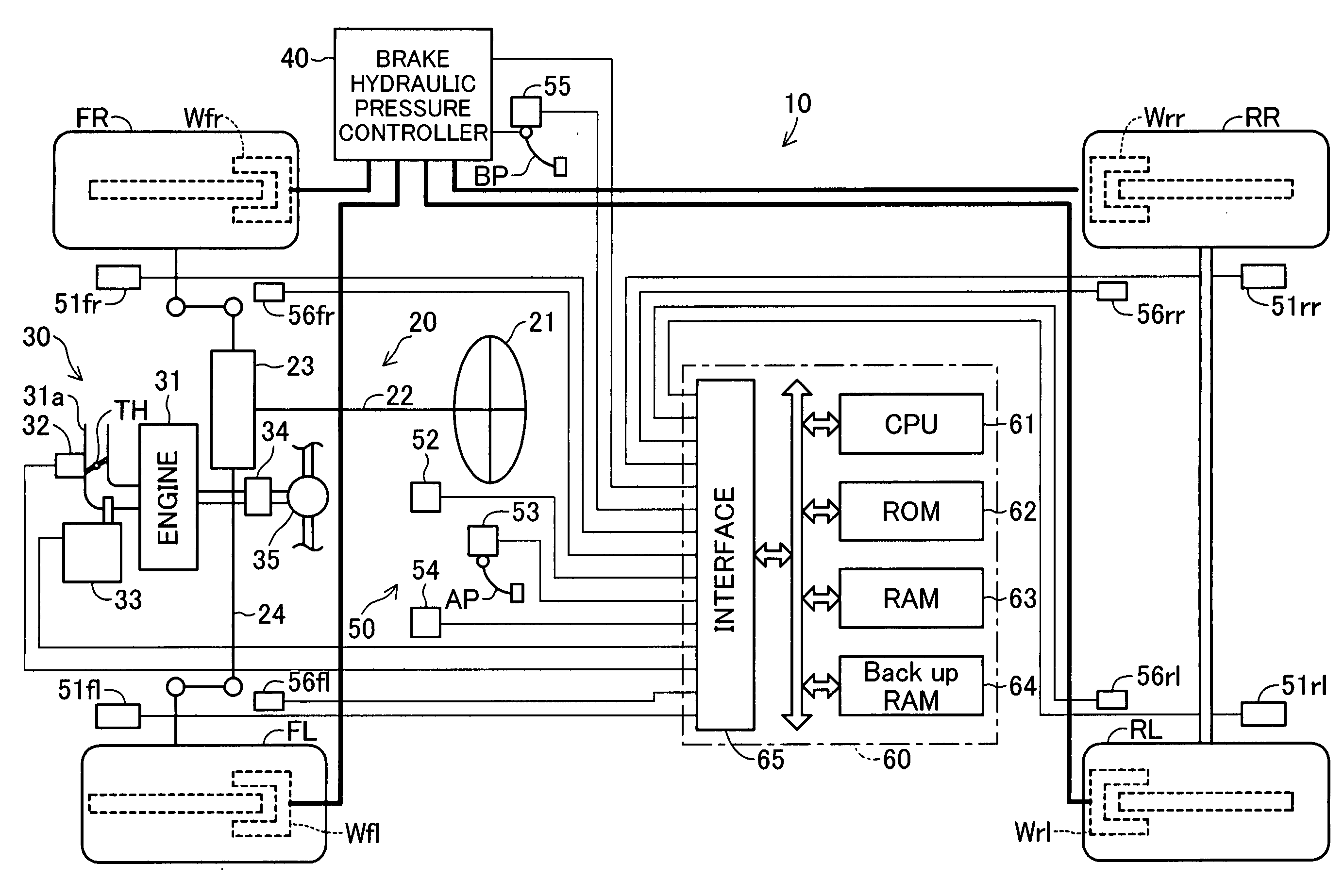
[0011] The present invention has been accomplished in order to solve the above-described problem, and an object of the present invention is to provide a motion control apparatus for a vehicle which can prevent the vehicle from rolling excessively, while more satisfactorily maintaining a desired turning locus tracing performance.

Problems solved by technology

As a result, in some cases a desired turning locus tracing performance cannot be maintained satisfactorily.

Method used


Image

  • Motion control apparatus for vehicle
  • Motion control apparatus for vehicle
  • Motion control apparatus for vehicle

Examples


case 1

[0112] the absolute value of the actual lateral acceleration Gy detected by means of the lateral acceleration sensor 54 is less than the rollover prevention control starting reference value Gyth and the absolute value of the lateral acceleration deviation ΔGy calculated in Step 510 of FIG. 5 is equal to or higher than the above-described ΔGy1 (that is, the OS-US suppression control is performed); and

case 2

[0113] the absolute value of the actual lateral acceleration Gy is equal to or higher than the rollover prevention control starting reference value Gyth (that is, the rollover prevention control is performed).

[0114] It is determined in Step 835 that the turning stability control is necessary, the CPU 61 proceeds to Step 840 so as to set the value of the variable Mode to 4 to thereby select a control mode for performing only the turning stability control (in actuality, either the OS-US suppression control or the rollover prevention control). Subsequently, the CPU 61 proceeds to Step 850. If it is determined in Step 835 that the turning stability control is not necessary, the CPU 61 proceeds to Step 845 so as to set the value of the variable Mode to zero to thereby select a non-control mode in which motion control for the vehicle is not carried out, and then proceeds to Step 850. In this case, a specified wheel which should be controlled does not exist.

[0115] When the CPU 61 proceed...


PUM


Abstract

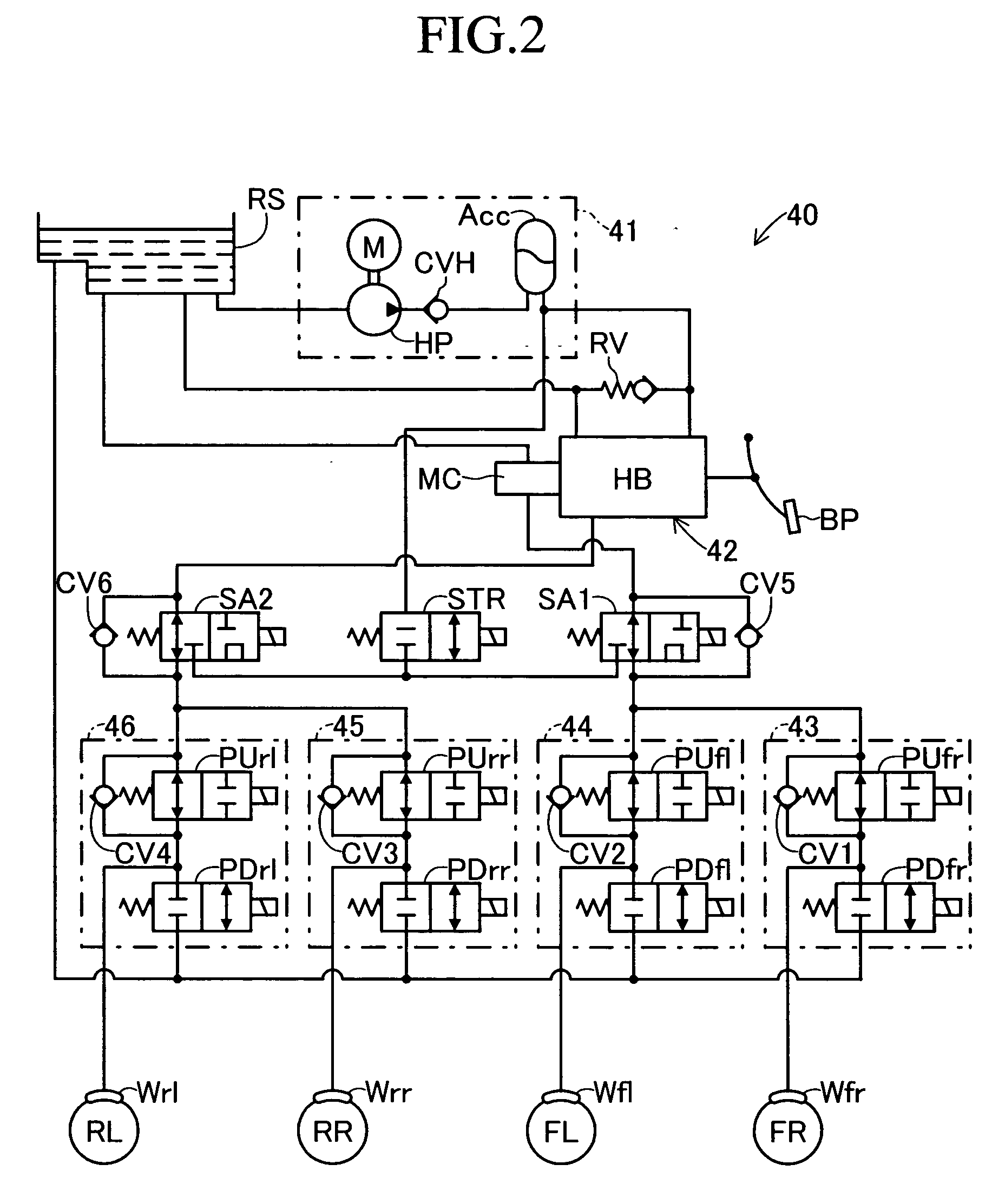
In rollover prevention control, an inner front wheel braking force is generated only in a front wheel located on the radially inner side of a turning locus in a relatively early stage where the absolute value of actual lateral acceleration is between a first value and a second value. When the absolute value becomes greater than the second value, in addition to the inner front wheel braking force, an inner rear wheel braking force is generated in a rear wheel located on the radially inner side of the turning locus. When the absolute value becomes greater than a third value, in addition to the inner rear wheel breaking wheel, an outer wheel braking force is generated in the front wheel located on the radially outer side of the turning locus. Thus, an increase in the roll angle is suppressed, and a desired turning locus tracing performance is maintained satisfactorily.

Description

CROSS REFERENCE TO RELATED APPLICATION [0001] This application is based on and claims under 35 U.S.C. sect, 119 with respect to Japanese Patent Application No. 2005-328240 filed on Nov. 14, 2005, the entire content of which is incorporated herein by reference. BACKGROUND OF THE INVENTION [0002] 1. Field of the Invention [0003] The present invention relates to a motion control apparatus for a vehicle which controls the motion of a vehicle by controlling the braking forces applied to the wheels of the vehicle. [0004] 2. Description of the Related Art [0005] For example, a motion control apparatus (braking apparatus) for a vehicle disclosed in Japanese Patent Application Laid-Open (kokai) No. H10-81215 applies a braking force (hereinafter referred to “outer wheel braking force”) to a wheel (e.g., front wheel) located on the radially outer side of a turning locus when (the absolute value of) an actual lateral acceleration acting on the vehicle becomes equal to or higher than a certain t...

Claims


Application Information

Patent Timeline
Patent Type & Authority Applications(United States)
IPC IPC(8): B60T8/24B60T8/1755
CPCB60T8/17554B60T2230/03
Inventor YASUTAKE, TOSHIOKATO, TOSHIHISATSUGAWA, SHINJI
Owner ADVICS CO LTD
Learn More