
Fire suppression system

a fire suppression system and fire suppression technology, applied in fire rescue and other directions, can solve the problems of unfavorable personnel safety, danger, injury and even death, and the control mechanism of the mechanism is unfavorable, and achieves the effect of simple and efficient design

Active Publication Date: 2007-05-24
MUNROE DAVID B
View PDF22 Cites 44 Cited by
  • Summary
  • Abstract
  • Description
  • Claims
  • Application Information

AI Technical Summary

Benefits of technology

[0013] In view of the above, there is a need for an improved fire suppression system which automatically activates with a simple, effective and reliable trigger mechanism to remove the danger of human operation. Further, a fire suppression system that is fully mobile for application on boats, other vehicles and locations without access to water distribution. Preferably, the system has a simple yet effective control mechanism for activation. Moreover, the system would prevent significant property damage. Preferably, the fire suppression system delivers a clean agent such as CAF that will cling to vertical surfaces and cools to prevent reflash. Further, a nozzle for delivering CAF and use in the trigger mechanism that has reliable operation in response to a change in an environmental parameter would be an improvement over the prior art.
[0015] In another embodiment, the system is design to vigorously generate CAF for release while being a simple and efficient design.

Problems solved by technology

Despite these advances, there are problems associated with the prior art.
Manual fire extinguishers are very mobile but if the fire is consuming the area, danger, injury and even death must be risked by the personnel in their efforts to deploy the fire suppressant.
Further, the delivery mechanism have control mechanisms that are unduly complex and damage the fire suppressing properties of CAF when passed therethrough.

Method used


Image

  • Fire suppression system
  • Fire suppression system
  • Fire suppression system

Examples


Embodiment Construction

[0030] The present invention overcomes many of the prior art problems associated with suppression systems for fire, biohazards and the like. The advantages, and other features of the systems disclosed herein, will become more readily apparent to those having ordinary skill in the art from the following detailed description of certain preferred embodiments taken in conjunction with the drawings which set forth representative embodiments of the present invention and wherein like reference numerals identify similar structural elements whenever possible.

[0031] Unless otherwise specified, the illustrated embodiments can be understood as providing exemplary features of varying detail of certain embodiments, and therefore, unless otherwise specified, features, components, modules, elements, and / or aspects of the illustrations can be otherwise combined, interconnected, sequenced, separated, interchanged, positioned, and / or rearranged without materially departing from the disclosed systems ...


PUM


Abstract

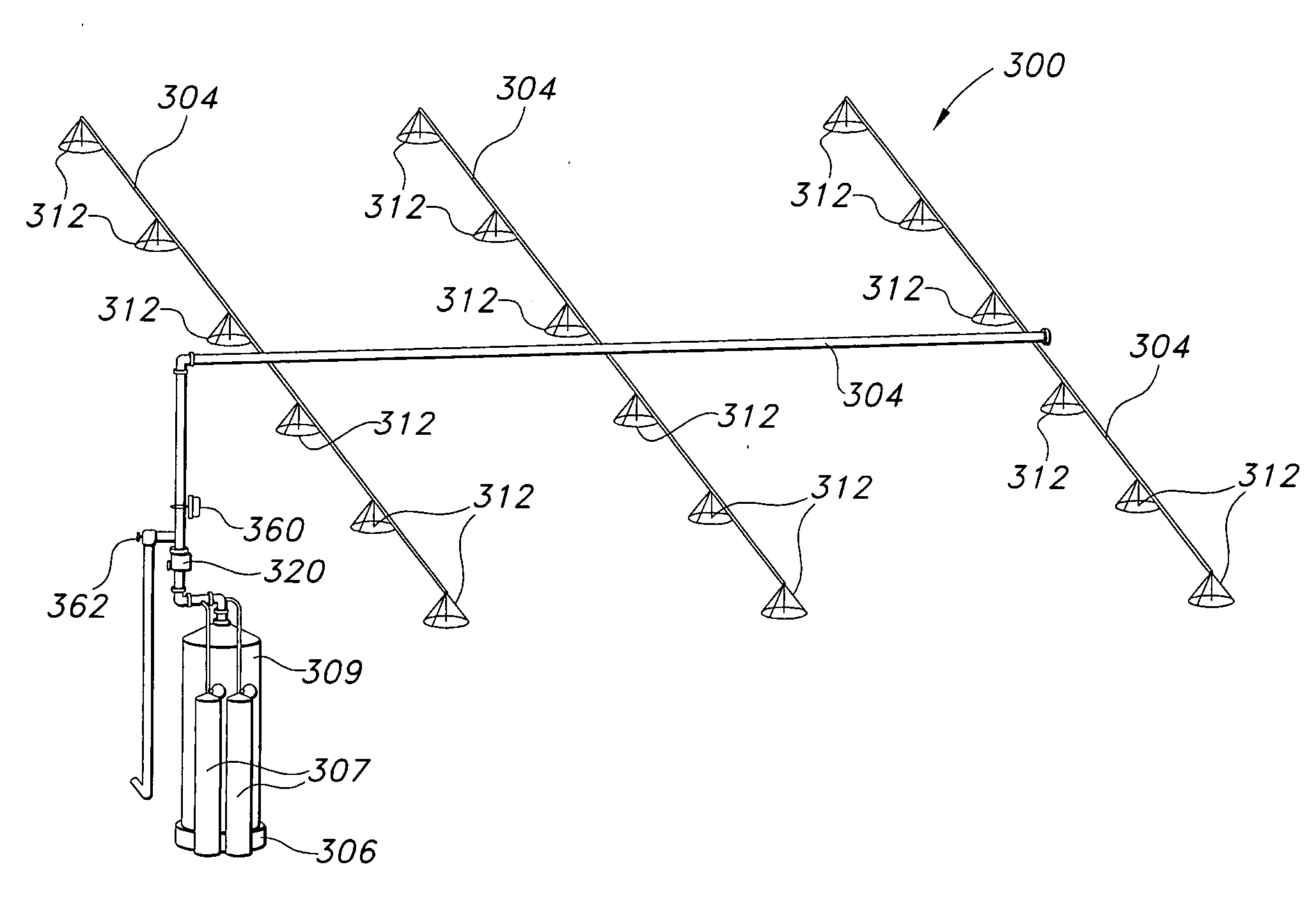
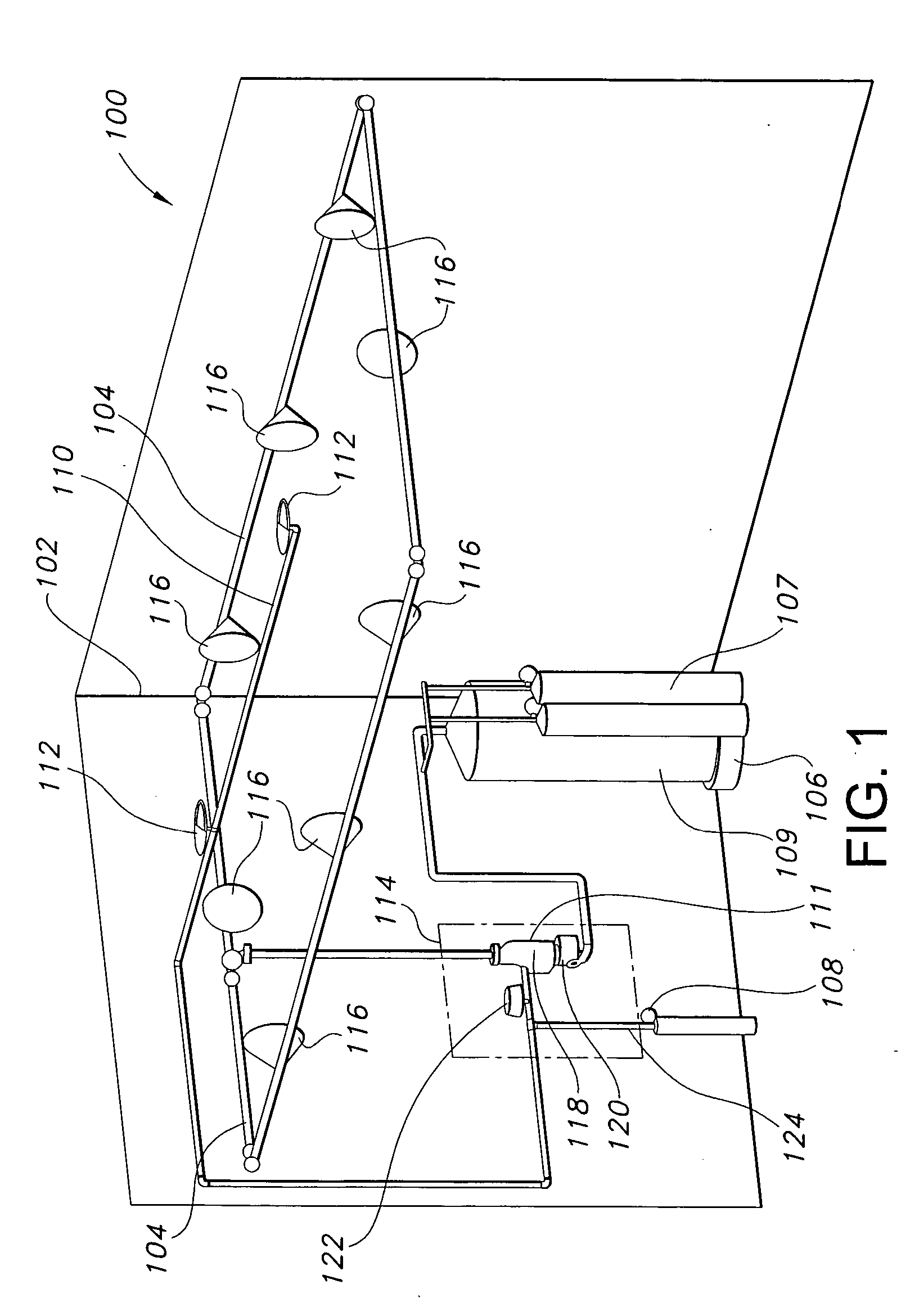
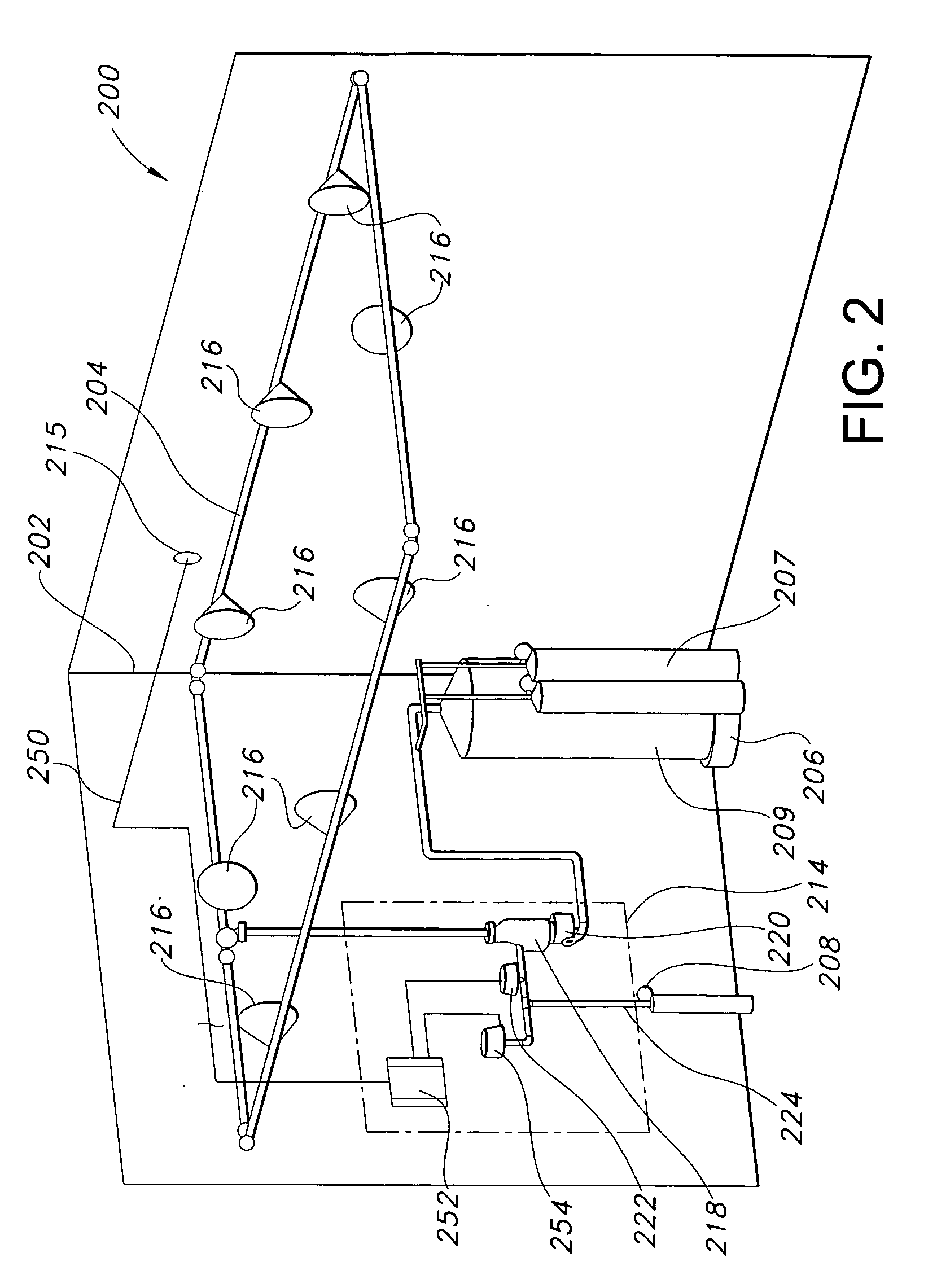
A fire suppressant system having a pipe system, spray nozzles connected to the pipe system and a control system for selectively charging the pipe system with foam. The control system includes a pilot line for generating a signal based upon sensing an environmental parameter and a first control valve for activating the system based upon the signal. Preferably, the first control valve forms i) an interior cavity for mixing the compressed air and compressed air liquid, ii) an outlet in fluid communication with the interior; iii) a first inlet, oriented substantially perpendicular to a flow through the outlet, in fluid communication with the interior and the compressed air; and iv) a second inlet, oriented substantially perpendicular to the flow, in fluid communication with the interior and the compressed air liquid.

Description

CROSS-REFERENCE TO RELATED APPLICATION [0001] This application claims priority to U.S. Provisional Patent Application No. 60 / 737,918, filed Nov. 18, 2005, and U.S. Provisional Patent Application No. 60 / 764,501 filed Feb. 1, 2006, each of which is incorporated herein by reference.BACKGROUND OF THE INVENTION [0002] 1. Field of the Invention [0003] The subject disclosure relates to systems for automatic fire suppression, and more particularly to an improved system for automatically delivering compressed air foam (CAF) to a hazard area that is typically difficult to safely and properly access. The systems are also effective for delivering foam and like substances to cover and control biohazards. [0004] 2. Background of the Related Art [0005] For centuries, man has battled unwanted fires. As technology has developed, the fire fighting techniques have matured from the bucket brigade to highly specialized vehicles, systems and chemicals. However, in many instances such as off-shore drillin...

Claims


Application Information

Patent Timeline
IPC IPC(8): A62C35/00
CPCA62C5/02A62C35/62
Inventor MUNROE, DAVID B.
Owner MUNROE DAVID B
Learn More