Confocal imaging methods and apparatus

a technology of optical imaging and confocal imaging, applied in the field of optical imaging, can solve the problems of insufficient attention to microarray imaging, advances that have not necessarily benefited high resolution scanning of substantially larger samples such as microarrays,

Active Publication Date: 2007-05-24
ILLUMINA INC
View PDF58 Cites 211 Cited by
  • Summary
  • Abstract
  • Description
  • Claims
  • Application Information

AI Technical Summary

Benefits of technology

[0008] The invention provides an imaging apparatus. The imaging apparatus can include (a) a radiation source positioned to send excitation radiation to at least a portion of a sample region; (b) a rectangular detector array; (c) imaging optics positioned to direct a rectangular image of the portion to the rectangular detector array; and (d) a scanning device configured to scan the sample region in a scan-axis dimension, whereby the portion of the sample region that forms a rectangular image at the rectangular detector array is changed, wherein the shorter of the two rectangular dimensions for the rectangular detector array and the shorter of the two rectangular dimensions for the image are in the scan-axis dimension, and wherein the shorter of the two rectangular dimensions for the rectangular detector array is short enough to achieve confocality in a single axis of the rectangular detector array, wherein the single axis is the shorter of the two rectangular dimensions for the rectangular detector array.
[0009] The invention further provides a method of obtaining an image of a sample. The method can include the steps of (a) contacting at least a first portion of a sample with excitation radiation under conditions wherein radiation is emanated from the first portion; (b) directing the radiation emanated from the first portion to form a rectangular image of the first portion at a rectangular detector array; and (c) scanning the sample region in a scan-axis dimension, thereby repeating steps (a) and (b) to form a rectangular image of a second portion of the sample at the rectangular detector array, wherein the shorter of the two rectangular dimensions for the rectangular detector array and the shorter of the two rectangular dimensions for the images are in the scan-axis dimension, and wherein the shorter of the two rectangular dimensions for the rectangular detector array is short enough to achieve confocality in a single axis of the rectangular detector array, wherein the single axis is the shorter of the two rectangular dimensions for the rectangular detector array.
[0010] The invention also provides a method of configuring a scanner to achieve confocality in a single axis. The method can include the steps of (a) providing an apparatus having (i) a radiation source positioned to send excitation radiation to at least a portion of a sample region; (ii) a rectangular detector array; (iii) imaging optics positioned to direct a rectangular image of the portion to the rectangular detector array; and (iv) a scanning device configured to scan the sample region in a scan-axis dimension, whereby the portion of the sample region that forms a rectangular image at the rectangular detector array is changed, wherein the shorter of the two rectangular dimensions for the rectangular detector array and the shorter of the two rectangular dimensions for the image are in the scan-axis dimension; and (b) positioning the rectangular detector array or the imaging optics to restrict the shorter of the two rectangular dimensions for the rectangular detector array to be short enough to achieve confocality in a single axis of the rectangular detector array, wherein the single axis is the shorter of the two rectangular dimensions for the rectangular detector array. The methods can be carried out using the apparatus described in further detail below. However, it will be understood that the method steps exemplified below with regard to particular apparatus can also be carried out using an alternative apparatus.

Problems solved by technology

Although microarray detection has benefited from advances in light microscopy, there are a number of areas that have not been addressed adequately in regard to microarray imaging.
These advances are favorable for imaging small samples, on the order of one or a few biological cells; however, the advances have not necessarily benefited high resolution scanning of substantially larger samples such as microarrays.

Method used


Image

  • Confocal imaging methods and apparatus
  • Confocal imaging methods and apparatus
  • Confocal imaging methods and apparatus

Examples


Embodiment Construction

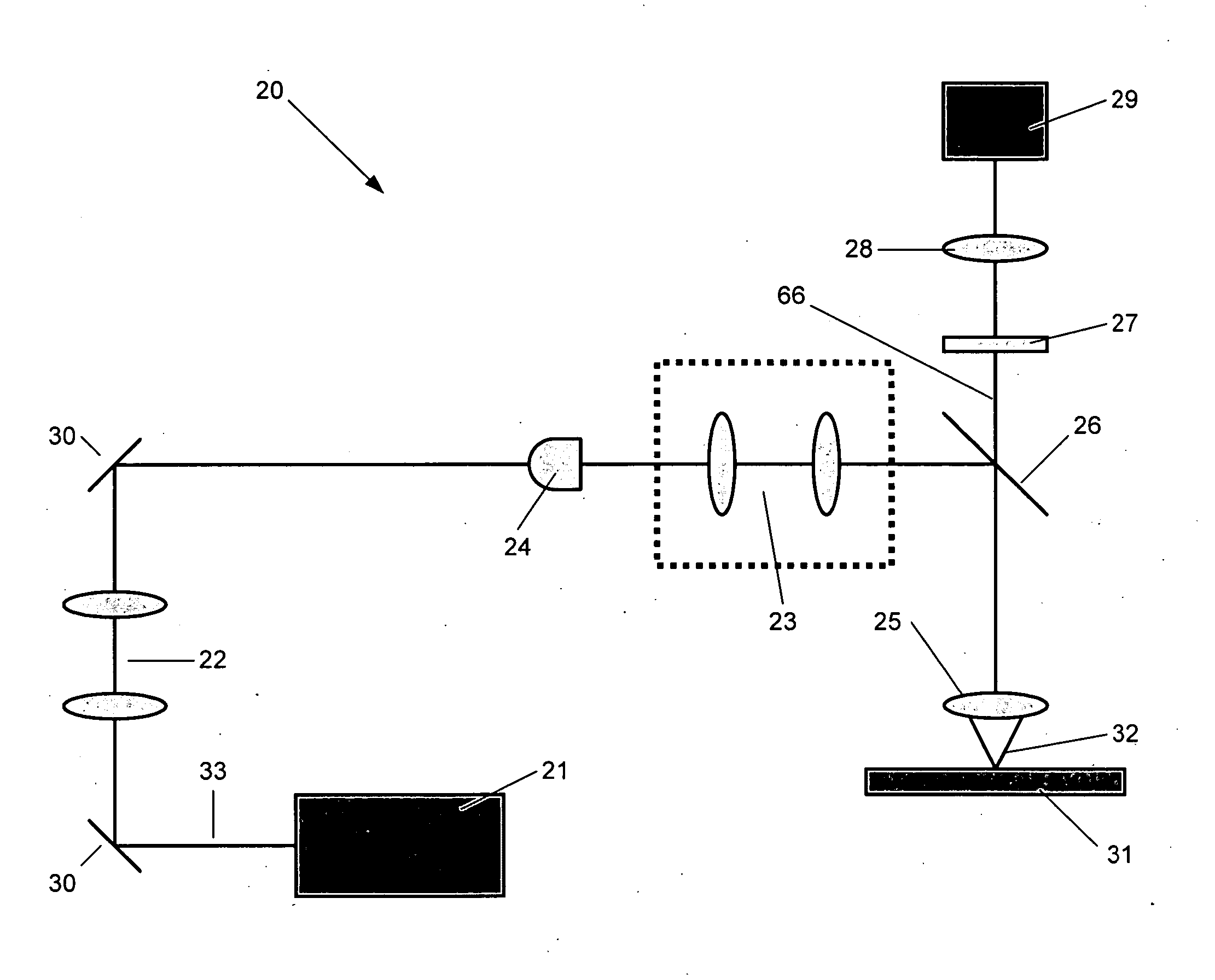
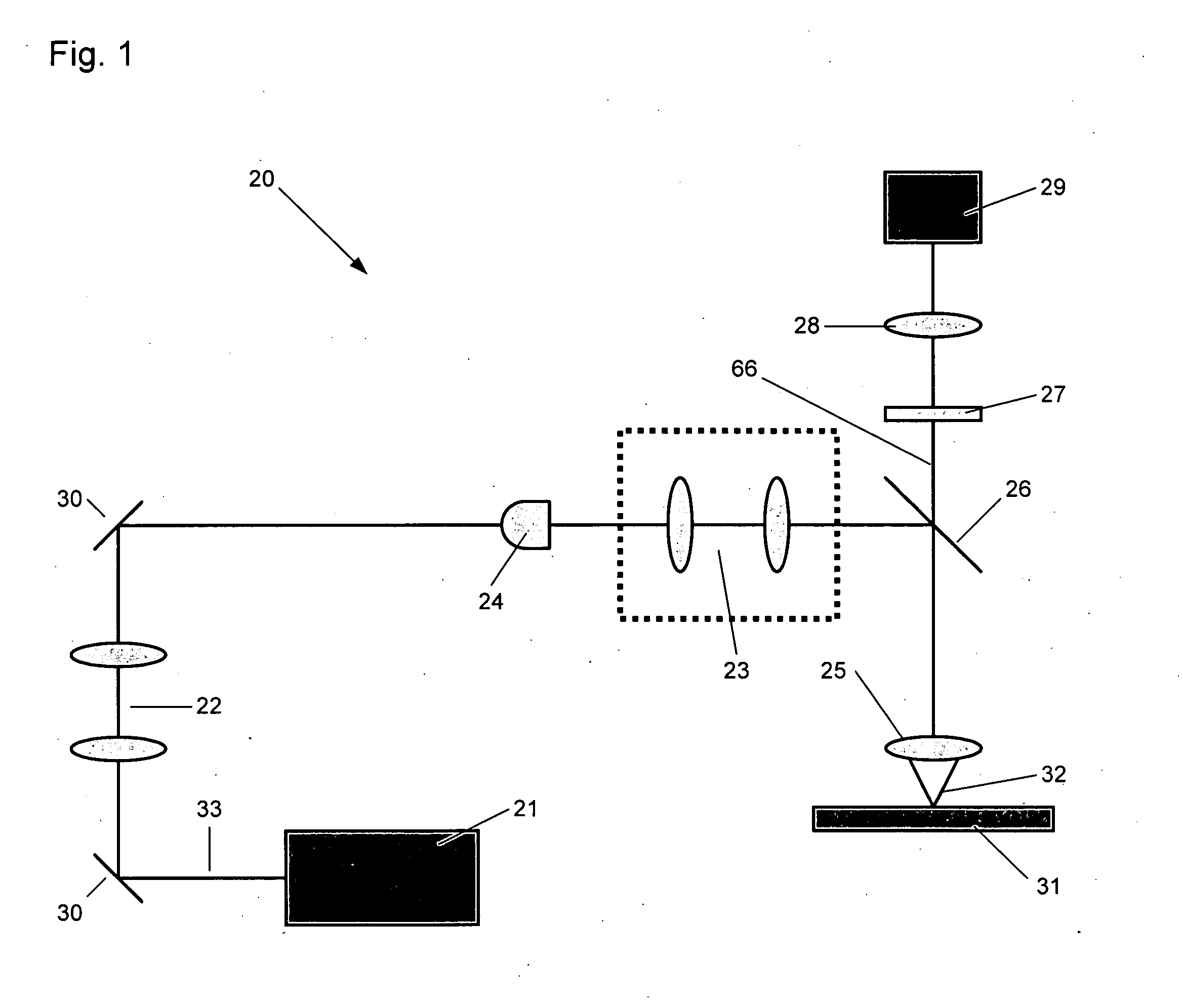
[0023] The present invention provides an image scanning system and architecture having rapid scan times while maintaining high resolution and image quality. These and other advantages result from configuring a detector array to achieve confocality in the scanning axis by restricting the scan-axis dimension of the detector array. As set forth in further detail below, an apparatus of the invention can be configured to achieve confocality in a single axis of a detector array such that confocality only occurs in that dimension. Thus, in contrast to typical confocal systems where confocality is achieved in two dimensions, an apparatus of the invention can be configured such that confocality is not achieved in more than one dimension.

[0024] The detector array can have rectangular dimensions such that the shorter dimension of the detector is in the scan-axis dimension. Imaging optics can be placed to direct a rectangular image of a sample region to the detector array such that the shorter...


PUM


Abstract

The invention provides imaging apparatus and methods useful for obtaining a high resolution image of a sample at rapid scan rates. A rectangular detector array having a horizontal dimension that is longer than the vertical dimension can be used along with imaging optics positioned to direct a rectangular image of a portion of a sample to the rectangular detector array. A scanning device can be configured to scan the sample in a scan-axis dimension, wherein the vertical dimension for the rectangular detector array and the shorter of the two rectangular dimensions for the image are in the scan-axis dimension, and wherein the vertical dimension for the rectangular detector array is short enough to achieve confocality in a single axis.

Description

BACKGROUND OF THE INVENTION [0001] The present invention relates generally to the field of optical imaging. Specifically, the present invention relates to imaging systems for use in detecting microarrays. [0002] Light microscopes provide a powerful tool for investigating samples at submicron resolution. For example, in biology and medicine, appropriate molecular tags, such as fluorescent and immunofluorescent tags, are used to label individual molecules and unique signals from the tags are detected by light microscope to identify their presence. Detection at submicron resolution allows not only determination of the presence of tagged molecules, but also their location in and around cells or tissues. [0003] Two conflicting goals of light microscopy inspection systems concern providing high speed imaging and high resolution imaging. Typically, the resolution of a light microscope is inversely proportional to the imaging speed. Thus, greater resolution is often achieved at the cost of ...

Claims


Application Information

Patent Timeline
Patent Type & Authority Applications(United States)
IPC IPC(8): H01L27/00
CPCG01N21/6428G01N21/6452G01N21/6458G01N21/6456G02B21/0032G02B21/004G01N2021/6421
Inventor FENG, WENYIKOTSEROGLOU, THEOFILOSWANG, MARKTRIENER, ALEXANDERCHE, DIPINGKAIN, ROBERT
Owner ILLUMINA INC
Why Eureka
Try Eureka