Ion beam device

Inactive Publication Date: 2007-05-24
NISSIN ION EQUIP CO LTD
View PDF2 Cites 21 Cited by
  • Summary
  • Abstract
  • Description
  • Claims
  • Application Information

AI Technical Summary

Benefits of technology

[0062] The sixteenth ion beam apparatus has an additional advantage of ability to enhance the energy separation performance to a much greater extent as a result of combination of the electrostatic deflector and the beam mask.
[0063] The seventeenth ion beam apparatus has an additional advantage of the speed-at which the ion beam ejected from the electrostatic deflector is scanned over a line in the scanning direction-becoming constant.
[0064] The eighteenth to twenty-sixth ion beam apparatuses have the following additional advantages. Specifically, the electrostatic deflector can decelerate the ion beam while deflecting it, thereby obviating a necessity for providing the deflector with a separate ion beam acceleration/deceleration device. Resultantly, when compared with a case where the deflector is provided with the separate ion beam acceleration/deceleration device, the beam line can be shortened. Therefore, a loss due to scattering of the ion beam, or the like, is diminished further, thereby enhancing the transport efficiency of the beam. Thus, ensuring a larger amount of beam is facilitated. Moreover, since the beam line can be shortened, the entire ion beam apparatus can be made more compact.
[0065] Particularly, in the case where the ion beam is decelerated, when the ion beam is caused to pass through the electrostatic deflector after having been completely decelerated to a desired energy level by the acceleration/deceleration device, the beam line at low energy is elongated, thereby increasing scattering of the ion beam due to the space charge effect. In contrast, acc

Problems solved by technology

Therefore, the length of the beam line of the ion beam has become longer, which in turn increases a loss due to divergence of the ion beam or a like cause.
As a result, a drop occurs in the transport efficiency of the ion beam, thereby resulting in difficulty in ensuring a sufficient quantity of a beam.
Particularly, the space-charge effect of the ion beam has noticeably appeared in transport of the ion beam at low energy, thereby diverging the ion beam and posing difficulty in efficient transport of the ion beam.
Accordingly, as mentioned previously, there still arises a problem of an increase in the length of the beam line.
For this reason, an iron core and a coil, which together constitute the deflection electromagnet, become very large, and hence the deflection e

Method used


Image

  • Ion beam device
  • Ion beam device
  • Ion beam device

Examples


Embodiment Construction

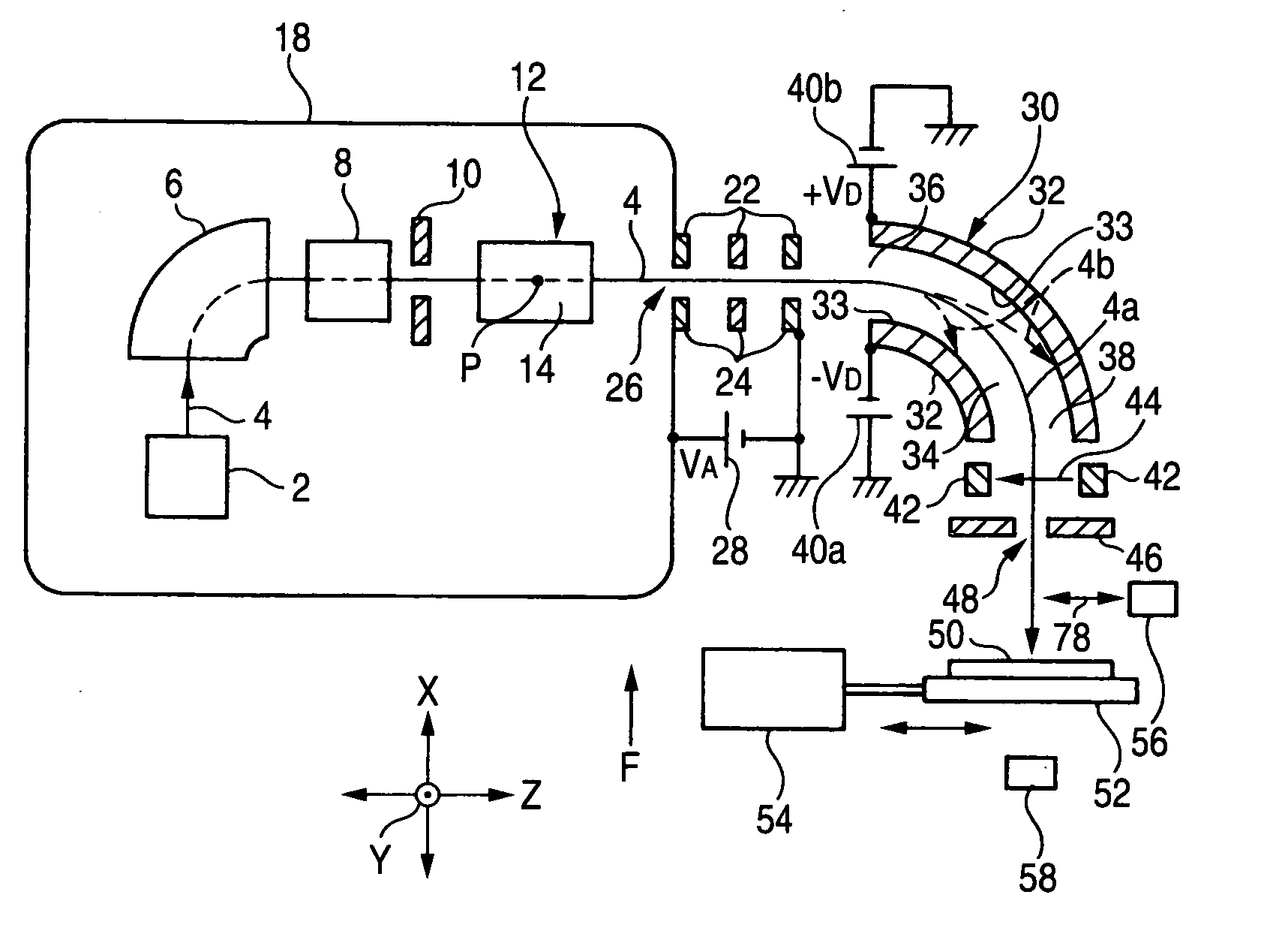
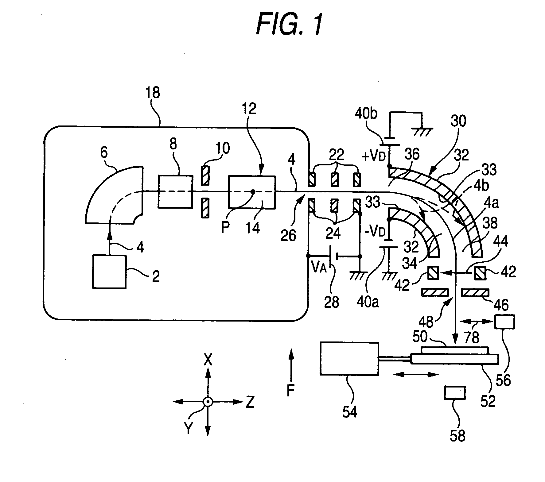
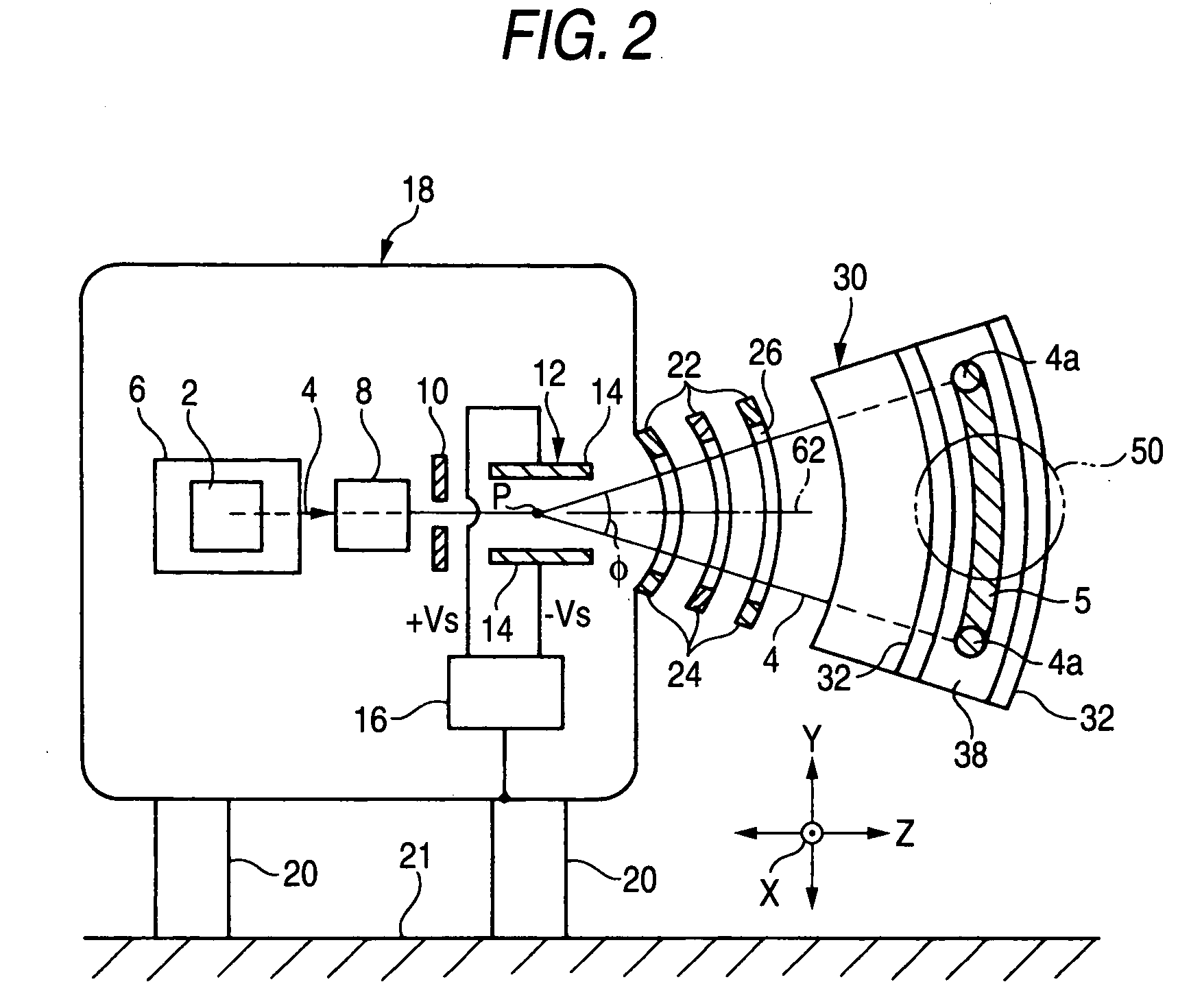
[0101]FIG. 1 is a plan view showing an embodiment of an ion beam apparatus (more specifically, an ion implantation apparatus) according to the present invention. FIG. 2 is a front view partially showing the ion beam apparatus shown in FIG. 1 when viewed in the direction of arrow F, showing a portion of the ion beam apparatus from an ion source to an exit of an electrostatic deflector. In the following descriptions, in an area of a path along which an ion beam 4 extracted from an ion source 2 travels, an area near to the ion source is called an “upstream area,” and an opposite area is called a “downstream area.”

[0102] This ion beam apparatus comprises the ion source 2 which extracts the ion beam 4; a mass separation electromagnet 6 which separates an ion beam 4 of a desired mass from the ion beam 4 extracted from ion source 2 (i.e., performs mass-separation of the ion beam 4); and a scanner 12 which scans the ion beam 4, which has passed through the mass separation electromagnet 6, w...


PUM


Abstract

An ion beam apparatus comprises an ion source 2 which extracts an ion beam 4, a mass separation electromagnet 6 which separates an ion beam 4 of desired mass from the ion beam 4 extracted from the ion source 2, a scanner 12 which scans the injected ion beam 4 with a given scan center as center within a given scan surface, an electrostatic deflector 30 which deflects the ion beam through 90° so that an ion beam of desired energy in said ion beam travels in a direction perpendicular to said scan surface within a circular-arc-shaped deflection zone centered on the scan center, and a scanning mechanism 54 which retains a target 50 and which mechanically, reciprocally moves the target 54 in a direction in which the target crosses the ion beam passed from the electrostatic deflector 30 at a given angle.

Description

TECHNICAL FIELD [0001] The present invention relates to an ion implantation apparatus which performs an ion implantation by means of irradiating an ion beam onto a target, and relates to an ion beam apparatus which constitutes the ion implantation apparatus and has a concept of encompassing an ion beam deflector for effecting scanning and deflection of the ion beam. More particularly, the present invention relates to an ion beam apparatus capable of shortening the length of an ion beam line. BACKGROUND ART [0002] In an ion beam apparatus (hereinafter typified by an ion implantation apparatus), such as an ion implantation apparatus, parallelism of an ion beam has hitherto been performed in order to make an incident angle of the ion beam uniform within a plane of a target (e.g., a semiconductor substrate). [0003] In order to prevent implantation, into the target, of ions of undesired energy (which will be referred to as “energy pollutants” or “energy contaminants”) (such implantation ...

Claims


Application Information

Patent Timeline
IPC IPC(8): H01J37/08G21K5/10H01J37/317H01J37/05H01J37/147
CPCH01J37/05H01J37/1477H01J2237/057H01J2237/053H01J37/3171
Inventor NAITO, MASAOFUJITA, HIDEKI
Owner NISSIN ION EQUIP CO LTD
Why Eureka
Try Eureka