Extensible end member for gas spring assembly

a gas spring and end member technology, applied in the direction of shock absorbers, mechanical equipment, transportation and packaging, etc., can solve the problems of unsatisfactory formation of leak paths, degeneration of otherwise substantially fluid-tight sealing arrangements, and damage to one or more components of the gas spring assembly,

Inactive Publication Date: 2007-05-24
FIRESTONE IND PROD COMPANY
View PDF21 Cites 48 Cited by
  • Summary
  • Abstract
  • Description
  • Claims
  • Application Information

AI Technical Summary

Problems solved by technology

The problems associated with overextending a gas spring assembly such that the flexible wall thereof is tensioned between the opposing end members are generally well known.
Such problems can include the undesirable formation of leak paths and the degeneration of otherwise substantially fluid-tight sealing arrangements.
In some circumstances, one or more components of the gas spring assembly can even become damages or otherwise adversely effected.
While various features of the restraining piston in the '128 patent provide other functional aspects of the air spring, the restraining piston also acts as a positive stop to prevent the flexible wall of the air spring from being tensioned and, thus, possibly damaged or otherwise adversely effected due to the occurrence of an overextended condition.
One difficulty with the foregoing and other known constructions that act to limit the distance that the end members of the air spring can be separated from one another is that in such constructions the length of the restraining piston will likely need to be related to the operative length of the flexible wall.
That is, if the length of the restraining piston is significantly greater than the fully extended length of the flexible wall, the restraining piston could be ineffective in protecting against overextension of the flexible wall.
Oppositely, if the length of the restraining piston is significantly less than the fully extended length of the flexible wall, the air spring could be incapable extending through the full functional range of the flexible wall.
It should be recognized that such arrangements can lead to increased production, assembly and inventory costs as well as other associated issues.
Another disadvantage of the foregoing and other known arrangements that act to limit the distance that the end members of the air spring can be separated from one another is that such extension-limiting devices are often formed within the spring chamber of the air spring.
This can reduce the active surface area of the air spring and result in reduced load capacity thereof.

Method used


Image

  • Extensible end member for gas spring assembly
  • Extensible end member for gas spring assembly
  • Extensible end member for gas spring assembly

Examples


Embodiment Construction

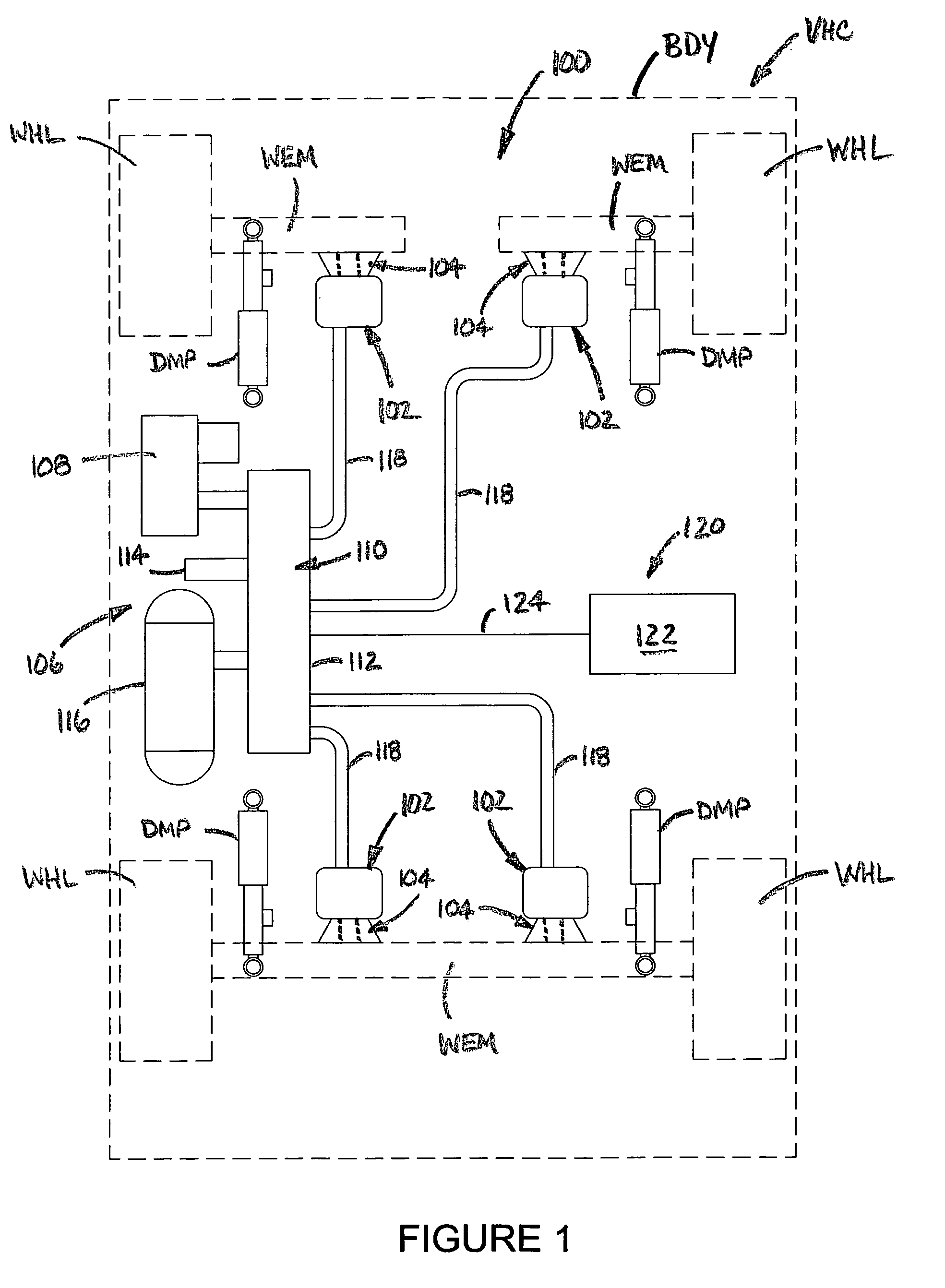
[0017] Turning now to the drawings, wherein the showings are for the purpose of illustrating exemplary embodiments of the present novel concept and not for the purpose of limiting the same, FIG. 1 illustrates one embodiment of a suspension system 100 disposed between a sprung mass, such as an associated vehicle body BDY, for example, and an unsprung mass, such as an associated wheel WHL or an associated wheel-engaging member WEM, for example, of an associated vehicle VHC. It will be appreciated that any such suspension system can include any number of one or more systems, components and / or devices and that the same can be operatively connected between the sprung and unsprung masses of the associated vehicle in any suitable manner. For example, such a suspension system can include a plurality of damping members, such as dampers DMP, for example, that can be operatively connected between the sprung and unsprung masses of the associated vehicle in any suitable manner.

[0018] Such a sus...


PUM


Abstract

A piston assembly used in forming a gas spring assembly includes a first piston member and a second piston member telescopically engaging one another and capable of axial displacement relative to one another between collapsed and extended conditions. The first piston member includes a mounting end and the second piston member includes a flexible wall-engaging end. The first and second piston members arranged such that in the collapsed condition the mounting and flexible wall-engaging ends are disposed a first distance from one another and in the extended condition the mounting and flexible wall-engaging ends are disposed at a second distance from one another with the second distance being greater than the first distance. A gas spring assembly and suspension system utilizing such a piston assembly as well as a method are also included.

Description

BACKGROUND [0001] The subject matter of the present disclosure broadly relates to the art of gas spring suspension systems and, more particularly, an extensible end member for use in forming with a gas spring assembly as well as a method of using the same. [0002] The subject matter of the present disclosure finds particular application and use in conjunction with suspension systems of wheeled vehicles, and will be shown and described herein with reference thereto. However, it is to be appreciated that the subject matter of the present disclosure is also amenable to other applications and environments, and that the specific uses shown and described herein are merely exemplary. For example, the subject matter of the present disclosure could be used in support structures, height adjusting systems and actuators associated with industrial machinery, components thereof and / or other such equipment. Accordingly, the subject matter of the present disclosure is not intended to be limited to u...

Claims


Application Information

Patent Timeline
Patent Type & Authority Applications(United States)
IPC IPC(8): F16F9/04
CPCB60G11/28B60G17/0155B60G17/0485B60G17/0523B60G2204/45B60G2206/424F16F9/05F16F9/057
Inventor MYERS, JAMES RICHARD
Owner FIRESTONE IND PROD COMPANY
Why Eureka
Try Eureka