Magnetic flux measuring apparatus by hysteresis characteristic type digital FLL using counter system for squid

a technology of magnetic flux and counter system, which is applied in the direction of magnetic measurement, magnetic field measurement using superconductive devices, instruments, etc., can solve the problems of large number of bits that cannot be assigned, the slew rate cannot be increased, and the inability to use expensive components capable of carrying out high-speed processing operations at a high bit rate or dsp

Inactive Publication Date: 2007-05-24
JAPAN SCI & TECH CORP
View PDF1 Cites 19 Cited by
  • Summary
  • Abstract
  • Description
  • Claims
  • Application Information

AI Technical Summary

Benefits of technology

[0016] The digital FLL apparatus, as shown in FIG. 1, uses only one counter 17. In the case where one counter is thus used in the digital FLL, the number of bits is restricted by the number of bits of hardware such as DSP (in general, a total number of 32 bits is used for counter bits and feedback bits). Thus, there has been a problem that a large number of bits cannot be assigned. In addition, in the case where the counter 17 is configured in a control computer, there is a need for transferring data within one shift. Thus, there has been a problem that a slew rate cannot be increased because a limitation depending on a data transfer speed applies.

Problems solved by technology

Thus, there has been a problem that a large number of bits cannot be assigned.
Thus, there has been a problem that a slew rate cannot be increased because a limitation depending on a data transfer speed applies.
Thus, there has been a problem that, in order to obtain a high resolution, a high slew rate and a high dynamic range, it is unavoidable to use expensive components capable of carrying out a high speed processing operation at a high bit rate or to use a DSP.
In this case, there is a problem that a stable operation cannot be made.
Thus, the operation becomes unstable.
In particular, there is a problem that, in a large noise environment or in the case where a signal frequently changes in the vicinity of a change point S, a frequent lock point change occurs.

Method used


Image

  • Magnetic flux measuring apparatus by hysteresis characteristic type digital FLL using counter system for squid
  • Magnetic flux measuring apparatus by hysteresis characteristic type digital FLL using counter system for squid
  • Magnetic flux measuring apparatus by hysteresis characteristic type digital FLL using counter system for squid

Examples


Embodiment Construction

[0048] Hereinafter, embodiments of the present invention will be described in detail with reference to specific examples shown in the accompanying drawings. An embodiment relating to the present invention will be described below. It is an object of the present invention to understand a general principle. Therefore, the present invention is not limited to only a configuration specifically described in the embodiment.

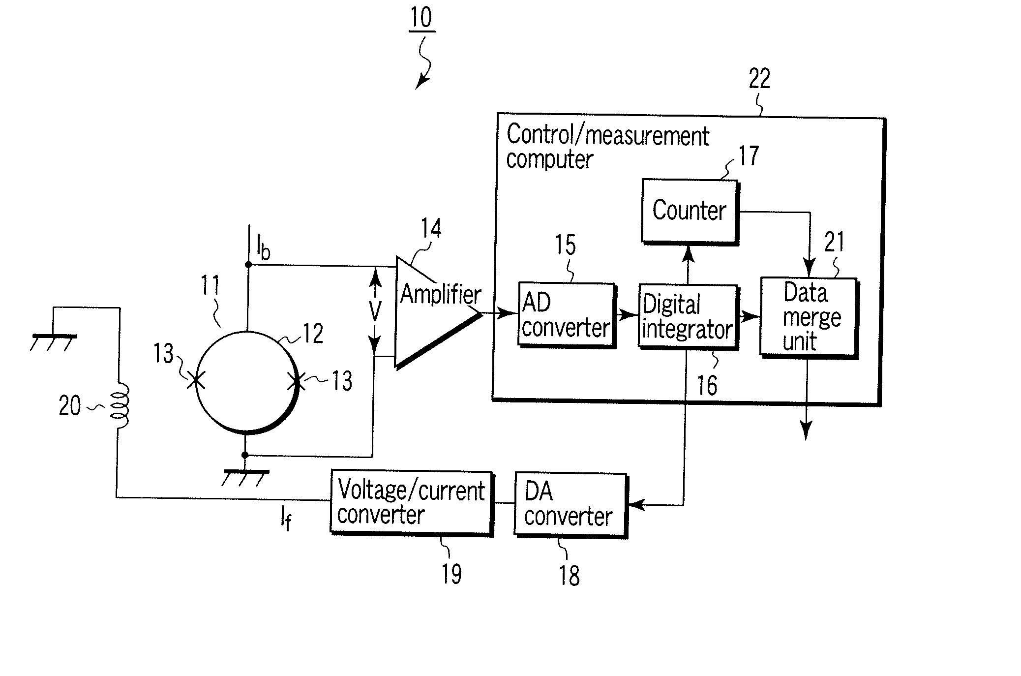
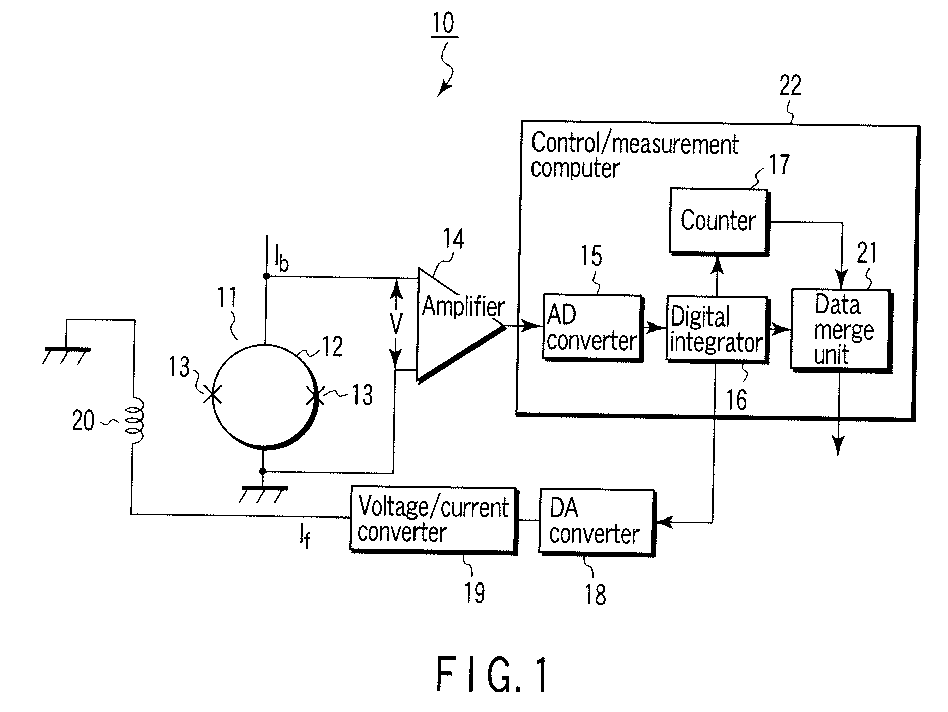
[0049]FIG. 4 shows a dcSQUID magnetometer 30 in accordance with a first embodiment of the present invention. As shown in FIG. 3, a SQUID 31 has a structure in which two Josephson junctions 33 have been provided partway of a ring 32 made of a superconducting material. For example, in the case of the SQUID using a high temperature superconducting material, a typical superconducting loop is formed to have thickness equal to or smaller than 1 μm, for example, to have a thin film of 0.2 μm. In addition, two junctions weak in a superconducting manner, each of which has a width...


PUM


Abstract

In a SQUID magnetometer, high resolution, a high slew rate, and a high dynamic range are achieved without using expensive circuit components having a large number of processing bits and enabling a high speed processing operation. A digital FLL circuit using a double counter system is provided. This circuit utilizes two or more counters, for example, a change range counter in a digital FLL for carrying out a processing operation at a high speed and a reproducing counter in a control/measuring computer. In addition, in the present invention, hysteresis characteristics having a 1Φ0 positive margin is used. That is, a change of a state of a magnetic flux is counted by means of a counter. At the time of this change, control is made so as to track a different channel between cases in which a magnetic flux increases and decreases, thereby stabilizing the control.

Description

CROSS REFERENCE TO RELATED APPLICATIONS [0001] This is a Continuation Application of PCT Application No. PCT / JP2005 / 010141, filed Jun. 2, 2005, which was published under PCT Article 21(2) in Japanese.[0002] This application is based upon and claims the benefit of priority from prior Japanese Patent Application No. 2004-165903, filed Jun. 3, 2004, the entire contents of which are incorporated herein by reference. BACKGROUND OF THE INVENTION [0003] 1. Field of the Invention [0004] The present invention relates to a magnetic flux detecting apparatus of a flux locked loop (FLL) system using a superconducting ring having a Josephson junction, i.e., a superconducting quantum interference device (SQUID). [0005] 2. Description of the Related Art [0006] An FLL system generally carries out measurement of a magnetic field by feeding a feedback current to a feedback coil additionally provided at the SQUID so that a value of a first defined lock point is maintained or so that a change rate of a ...

Claims


Application Information

Patent Timeline
Patent Type & Authority Applications(United States)
IPC IPC(8): G01R33/02G01R33/035
CPCG01R33/0354G01R33/0356Y10S505/846
Inventor KOBAYASHI, KOICHIROOYAMA, DAISUKEYOSHIZAWA, MASAHITONAKAI, KENJISIMIZU, TAKAYUKIUEDA, TOMOAKI
Owner JAPAN SCI & TECH CORP
Why Eureka
Try Eureka