Supercharge Your Innovation With Domain-Expert AI Agents!

High density three-dimensional RF / microwave switch architecture

a three-dimensional, high-density technology, applied in the field of rf switches, can solve the problems of affecting the performance of the switch, degrading the switch performance, and limited rf and microwave applications of any dimension, and achieve the effect of facilitating the assembly of the rf switch system

Active Publication Date: 2007-05-24
HARRIS GLOBAL COMM INC
View PDF6 Cites 8 Cited by
  • Summary
  • Abstract
  • Description
  • Claims
  • Application Information

AI Technical Summary

Benefits of technology

The invention is about a RF switching system that is made up of a structure made of dielectric material. The structure has multiple faces, with at least one face located in a plane exclusive of another face. The structure can be shaped like a polyhedron, with one face being perpendicular to another face. The system also includes RF switches that can be positioned on or adjacent to the faces of the structure. The RF switches can be MEMS devices, with conductive RF feed stubs and interconnection points. The system also has a transmission line for communicating RF energy and a control circuit for controlling the operation of the RF switches. The RF switch system can be mounted on a board made of dielectric material, which makes it easier to assemble the switch systems into an array.

Problems solved by technology

Still, existing single pole multiple throw switches for RF and microwave applications of any dimension are often limited with regard to the number of throws that can be provided without adversely affecting switch performance.
Increasing the number of paths often tends to degrade the switch performance and increase switch size.
One performance limiting factor for single-pole multiple-throw (SPMT) and multiple-pole multiple-throw (MPMT) type RF switches arises from relatively long stub lengths as compared to wavelength of interest.
Long stub lengths required for communicating RF to and from MEMS switches tends to be largely unavoidable in current architectures due to the generally planar layout of such devices.
Close spacing of MEMS switches in particular also can be a problem because of the difficulty associated with shielding actuation mechanisms.
For example, actuation of one magnetically actuated switch can inadvertently result in activation of an adjacent switch.
However, even these layered MEMS designs have not managed to increase the number of throws beyond about 14 without significant performance degradation, size and cost penalties.

Method used


Image

  • High density three-dimensional RF / microwave switch architecture
  • High density three-dimensional RF / microwave switch architecture
  • High density three-dimensional RF / microwave switch architecture

Examples


Embodiment Construction

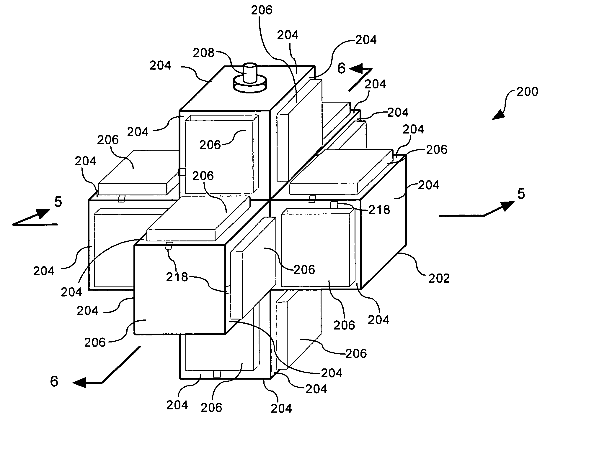
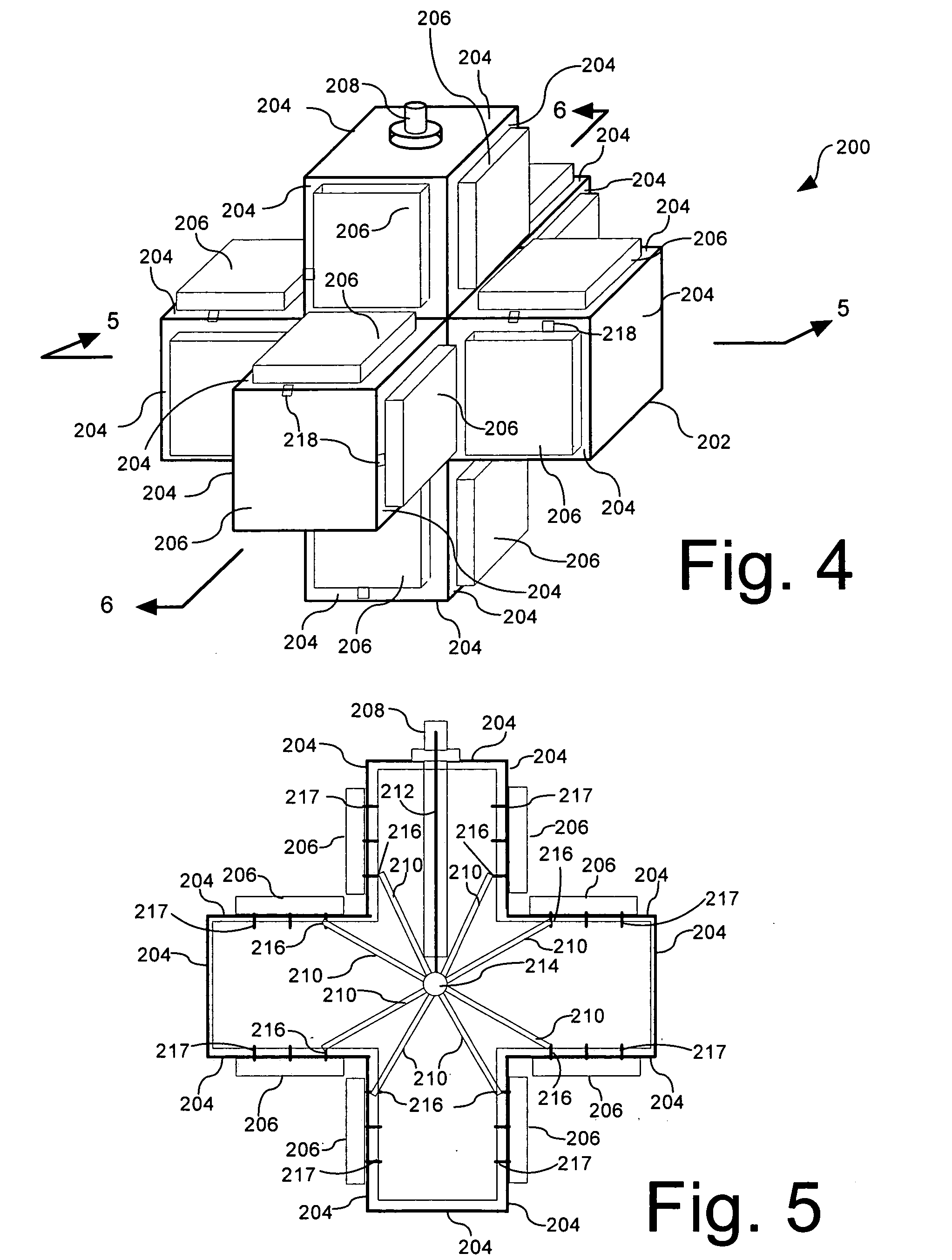
[0022]FIG. 1 shows an embodiment of an RF switching system 100. The RF switching system 100 can be formed from a structure 102 comprised of dielectric material. In general, the structure can have two or more faces 104, with at least one face located in a plane exclusive of a remainder of the faces. In FIG. 1, the structure 102 is shown as a cube. However, the invention is not limited in this regard. For example, the structure 102 can have any 3-dimensional geometric polyhedron form. As used herein, the term polyhedron refers to any three dimensional object that is bounded by a plurality of polygon shapes. According to one embodiment, at least a first one of the faces 104 can have an orientation that is generally orthogonal relative to at least a second one of the faces 104. According to another aspect of the invention, the polyhedron can be an orthogonal polyhedron. An orthogonal polyhedron is a polyhedron each of whose faces is perpendicular to a coordinate axis. The cube shown in ...


PUM


Abstract

RF switching system (100, 200) formed from a structure (102, 202) comprised of dielectric material. The structure can have two or more faces (104, 204), with at least one face located in a plane exclusive of at least a second one of the faces. For example, the structure can define a geometric shape that is a polyhedron. RF switches (106, 206) can be disposed on two or more of the faces. Conductive RF feed stubs (110, 210) are provided for each RF switch extending from an interconnection point (114, 214) to electrical contact terminals (116, 216) that are respectively connected to the RF switches. The interconnection point is located within the structure at a location generally medial to the two or more of terminals.

Description

STATEMENT REGARDING FEDERALLY SPONSORED RESEARCH OR DEVELOPMENT [0001] This invention was made with government support under Contract No. FA8709-04-C-0010. The government has certain rights in the invention.BACKGROUND OF THE INVENTION [0002] 1. Statement of the Technical Field [0003] The inventive arrangements relate generally to RF switches, and more particularly to high density microwave switch architectures. [0004] 2. Description of the Related Art [0005] RF / microwave switches are used in a wide variety of applications. For example, they can be used for switching multiple inputs to multiple outputs, routing of RF signals, selecting a particular input for a device from among multiple input signal sources, and switching a particular device into and out of a circuit. Various techniques are known for implementing RF switching. For example, PIN diodes are often used for this purpose. Developments in Micro-Electro-Mechanical Systems (MEMS) also include RF switching devices that demonst...

Claims


Application Information

Patent Timeline
Patent Type & Authority Applications(United States)
IPC IPC(8): H01P1/10
CPCH01P1/127
Inventor KHAZANOV, ALEKSANDR
Owner HARRIS GLOBAL COMM INC
Features
  • R&D
  • Intellectual Property
  • Life Sciences
  • Materials
  • Tech Scout
  • Unparalleled Data Quality
  • Higher Quality Content
  • 60% Fewer Hallucinations
Learn More