
Controlling buffer states in video compression coding to enable editing and distributed encoding

a technology of video compression and buffer state, applied in the field of video encoders, can solve the problems of remote decoder buffer entering an underflow or overflow condition, the performance of a single encoder engine can be inadequate and inefficient, and the system of encoder engine cannot account for the state of a remote decoder buffer

Inactive Publication Date: 2007-05-24
APPLE INC
View PDF87 Cites 54 Cited by
  • Summary
  • Abstract
  • Description
  • Claims
  • Application Information

AI Technical Summary

Problems solved by technology

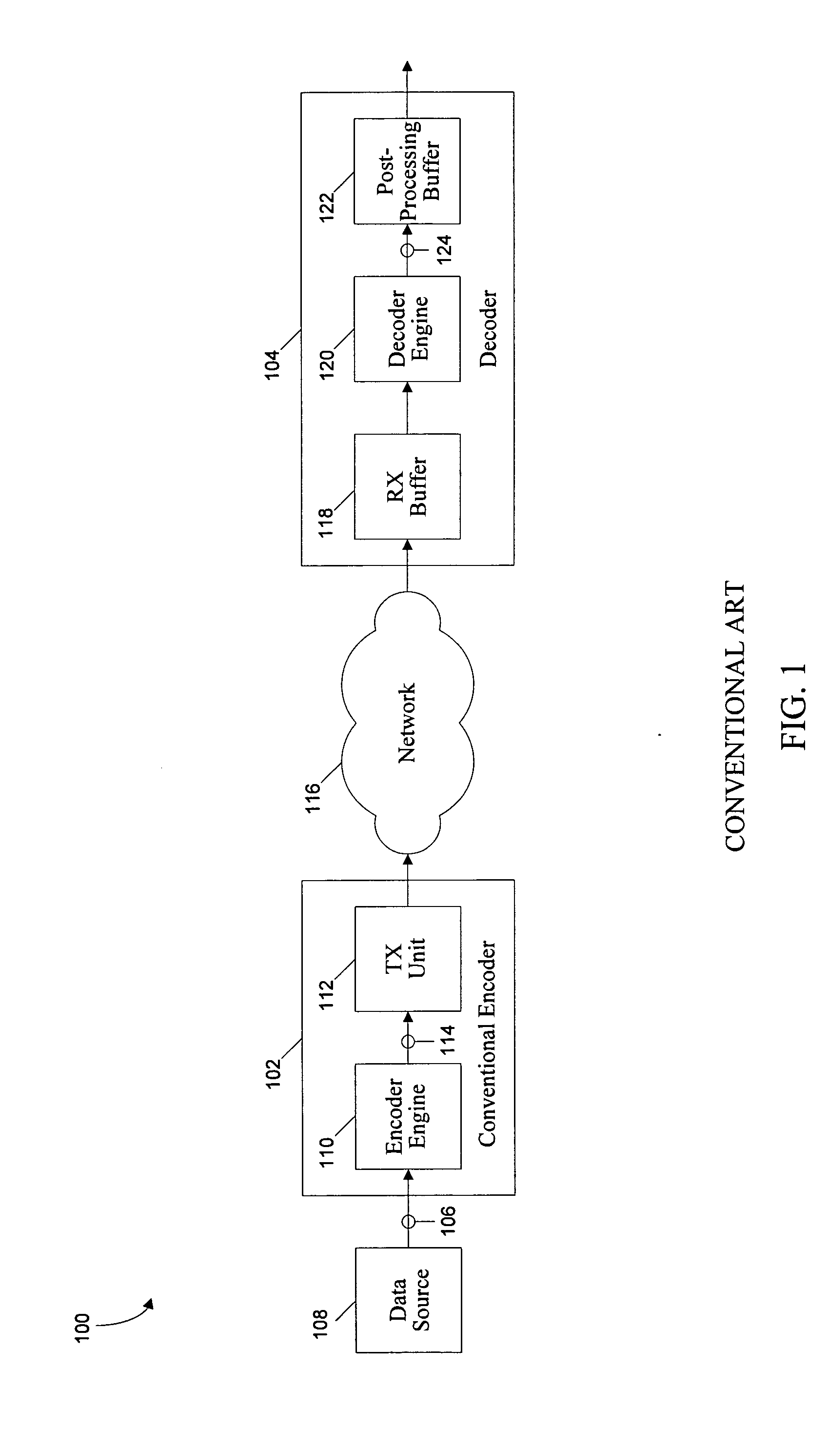
For long sequences of digital data, the performance of a single encoder engine can be inadequate and inefficient.
These multiple encoder engine systems, however, could not account for the state of a remote decoder buffer because such states would depend in part upon coding decisions by each encoder (to which the other encoders do not have access).
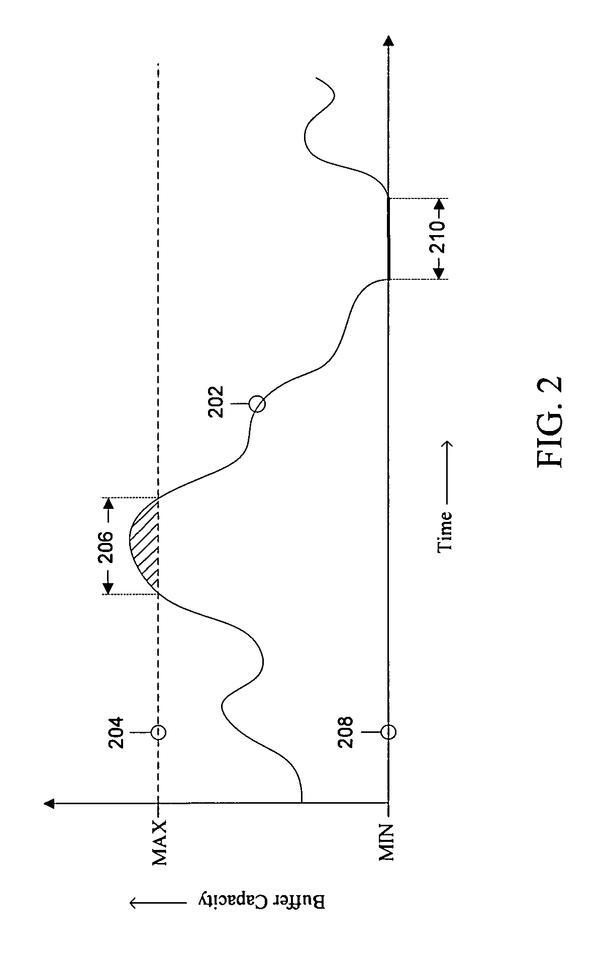
Consequently, the assembled encoded segments can cause the remote decoder buffer to enter an underflow or overflow condition.
In turn, the decoding process used to recover the original digital data is impaired.
Specifically, the decoding and / or associated rendering process can be stalled or distorted.
During an overflow, portions of the encoded data stream 114 can be lost, thereby hampering or degrading the quality of the decoding process.
An overflow condition experienced during video decoding, for example, can cause observable discontinuities in a rendered display of the decoded data.
An underflow condition experienced during video decoding, for example, can cause the decoding process to be disrupted or stalled.
However, because only a single encoder engine 110 is used to encode the source data 106, the multiple pass encoding process implemented by the conventional encoder 102 is slow and inefficient.

Method used


Image

  • Controlling buffer states in video compression coding to enable editing and distributed encoding
  • Controlling buffer states in video compression coding to enable editing and distributed encoding
  • Controlling buffer states in video compression coding to enable editing and distributed encoding

Examples


Embodiment Construction

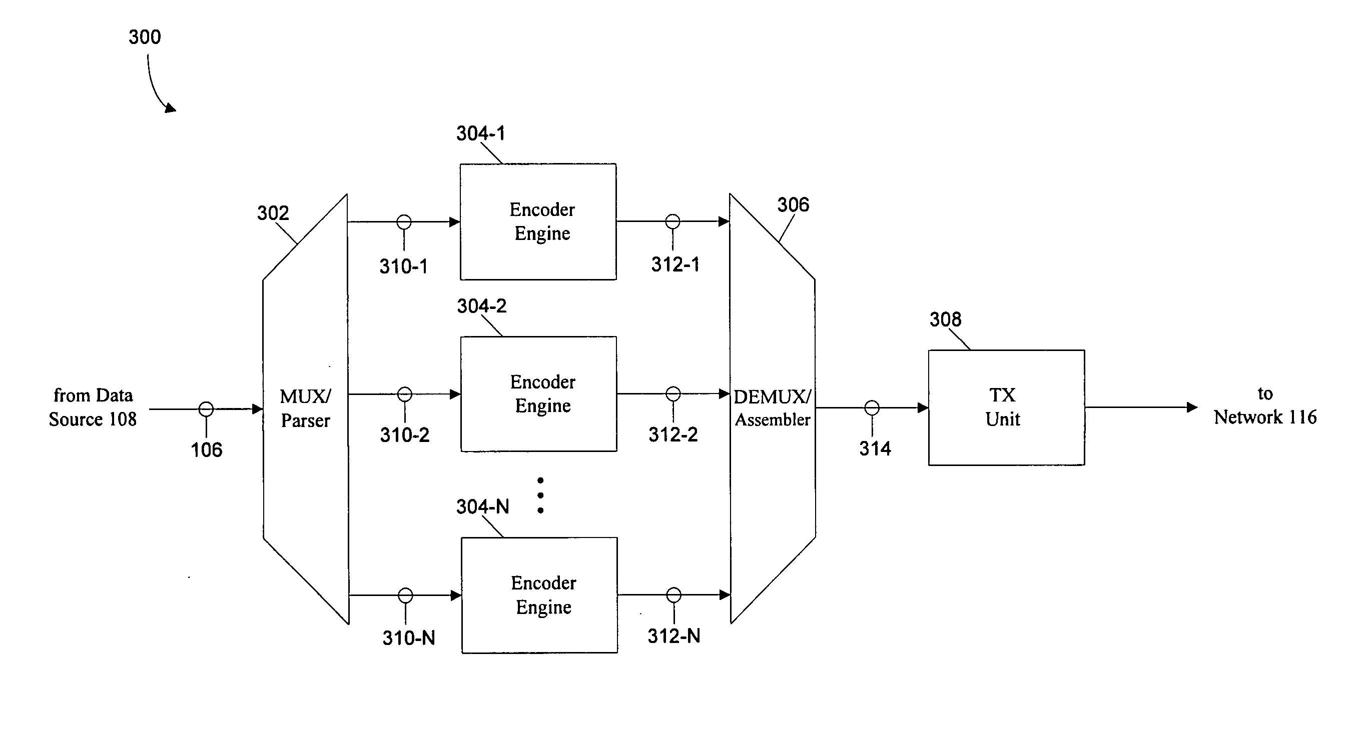
[0029] Embodiments of the present invention provide apparatuses and methods whereby independent encoder engines are compelled to code their respective parsed segments so that, at segment boundaries, the buffer status of an associated decoder is forced to some predetermined value (such as a half full state). Embodiments of the present invention provide apparatuses and methods whereby independent encoder engines are compelled to code their respective parsed segments so that, at segment boundaries, the buffer status of an associated decoder is forced to be within some predetermined range of values (such as a MIN and MAX range centered about a half full state). In this regard, the present invention enables independent encoders to encode separate segments of a large digital data stream to reduce processing time while ensuring a remote decoder buffer avoids underflow and overflow conditions.

[0030]FIG. 3 illustrates an encoder 300 capable of separately encoding multiple segments of an inp...


PUM


Abstract

An encoder includes a parser, a plurality of encoder engines and an assembler. The parser divides a portion of a received digital data stream into a plurality of segments having a begin boundary and an end boundary. The plurality of encoder engines independently encode the plurality of segments to accommodate a begin buffer status condition corresponding to each begin boundary and an end buffer status condition corresponding to each end boundary, thereby producing a plurality of corresponding encoded segments. The assembler combines the plurality of encoded segments to form a portion of an encoded digital data stream. The encoder engines verify the begin and the end buffer status conditions are satisfied for each encoded segment and also verify each encoded segment prevents an overflow and an underflow of a modeled decoder buffer. Any violating segment is re-encoded and re-verified prior to assembly.

Description

CROSS REFERENCE TO RELATED APPLICATIONS [0001] This application claims priority to U.S. Provisional Patent Application No. 60 / 737,804, filed Nov. 18, 2005, herein incorporated by reference in its entirety.BACKGROUND OF THE INVENTION [0002] 1. Field of the Invention [0003] The present invention generally relates to video encoders. More specifically, the present invention provides the independent encoding of multiple segments of a digital data stream to produce an encoded digital data stream. [0004] 2. Background Art [0005] Encoder-decoder systems are used to efficiently transfer digital information. Many encoders model the performance of an associated decoder, in particular the buffer states therein, to confirm the associated decoder will operate properly. In many instances, a single encoder engine is used to encode an entire digital data stream. For long sequences of digital data, the performance of a single encoder engine can be inadequate and inefficient. Accordingly, multiple ind...

Claims


Application Information

Patent Timeline
IPC IPC(8): H04N7/12
CPCH04N19/172H04N19/61H04N19/124H04N19/436H04N19/164H04N19/192H04N19/152
Inventor TONG, XINWU, HSI-JUNGHASKELL, BARIN GEOFFRY
Owner APPLE INC
Learn More