Celestial compass

a technology of compass and telescope, applied in the field of compass, can solve the problems of limited azimuth precision and very high precision of celestial objects measurement, and achieve the effect of accurate determination of the azimuth of an instrument, high precision and easy identification

Inactive Publication Date: 2007-05-24
TREX ENTERPRISES CORP
View PDF13 Cites 32 Cited by
  • Summary
  • Abstract
  • Description
  • Claims
  • Application Information

AI Technical Summary

Problems solved by technology

Measurements of celestial objects are known to very high precision, so the azimuth precision is limited mainly by the precision of the optics used to view them.

Method used


Image

  • Celestial compass
  • Celestial compass
  • Celestial compass

Examples


first preferred embodiment

Location of Celestial Objects

The Celestial Compass

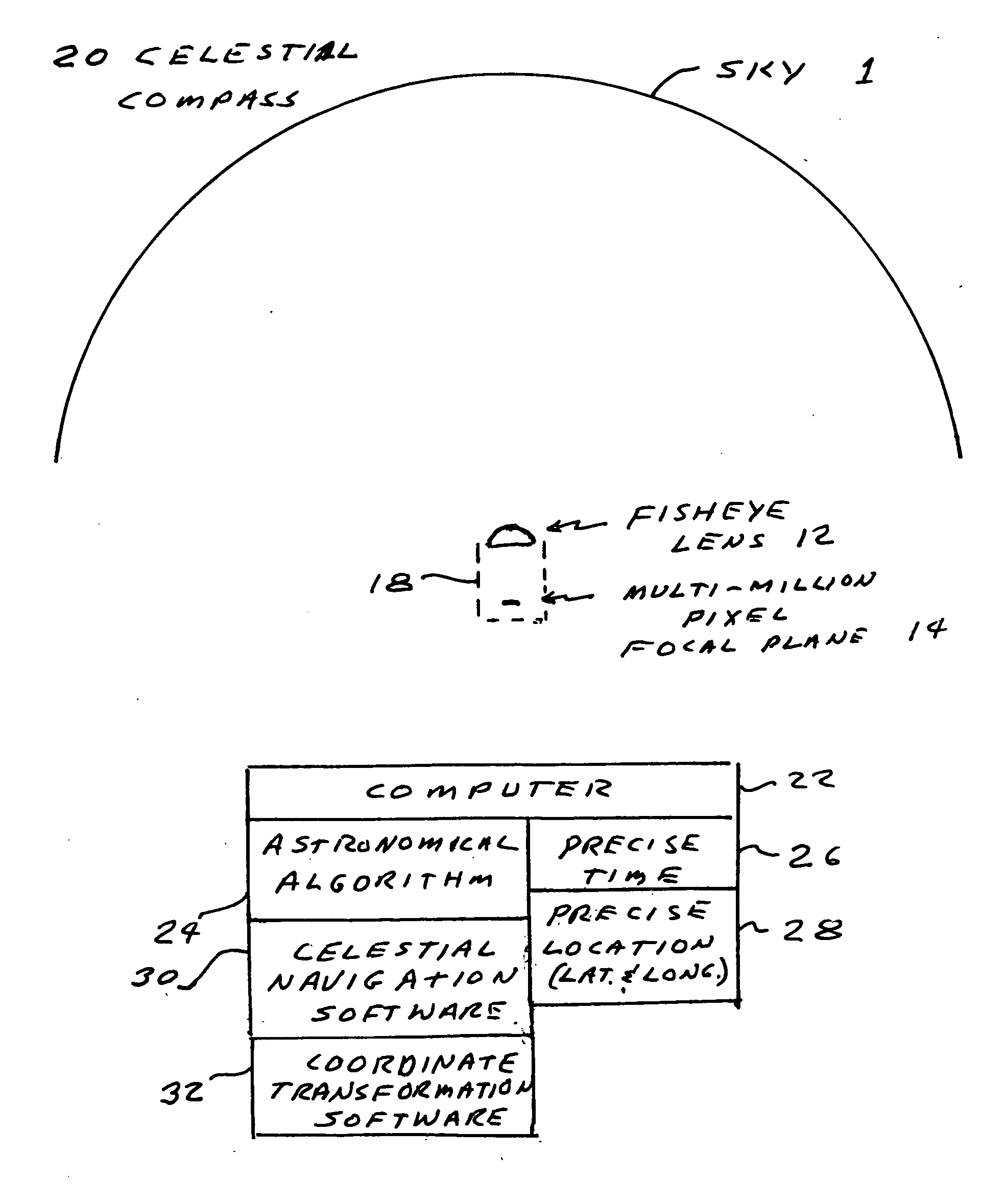
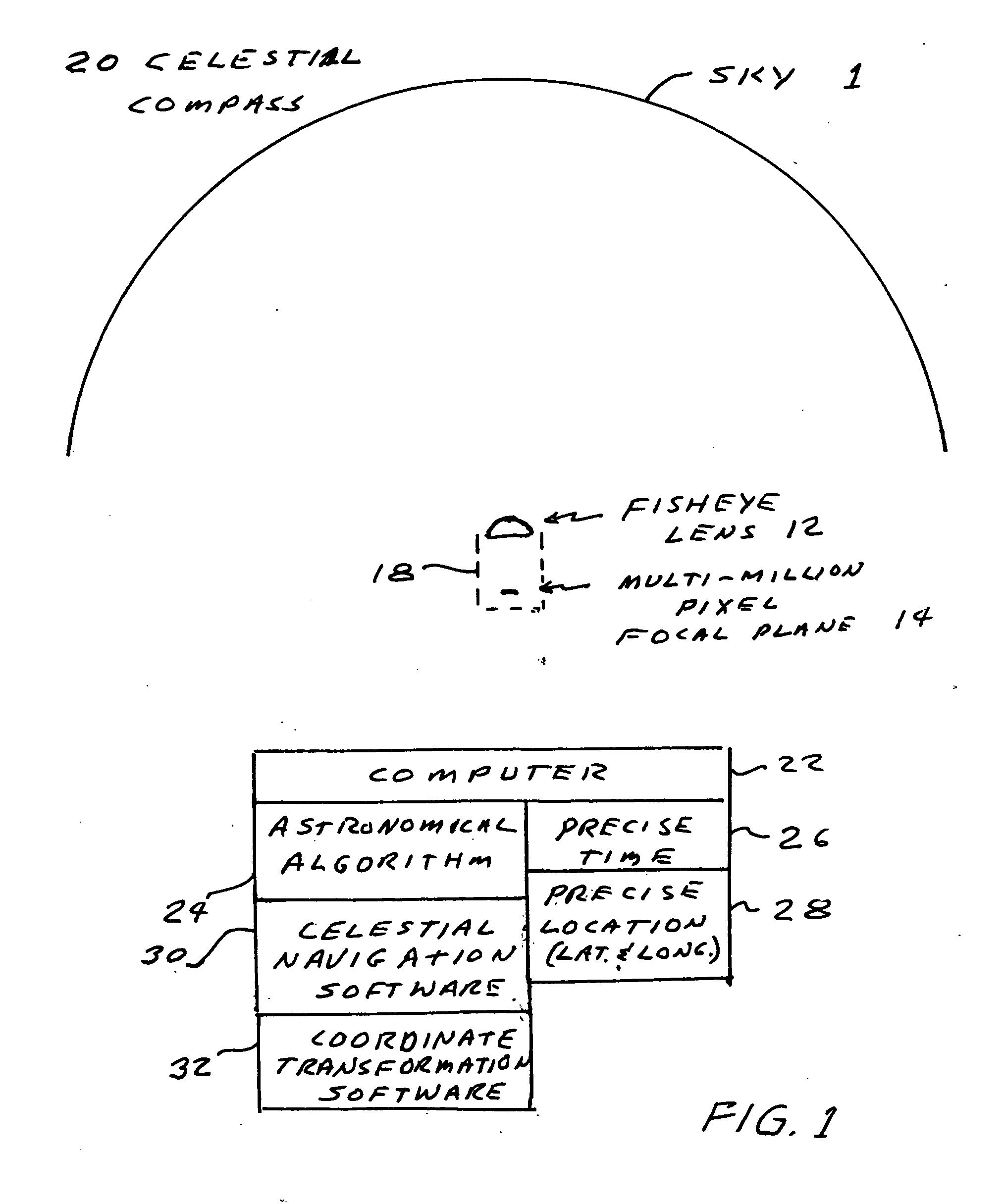
[0011] A first preferred embodiment of the present invention is shown in FIG. 1. It is a celestial compass and includes a camera 18 having a fisheye lens 12 suitable for viewing almost an entire hemisphere of the sky and a 6-million pixel sensor for collecting images of celestial objects such as stars, planets, the moon and the sun. The compass also includes a computer 22 programmed with an astronomical algorithm for providing the precise position of celestial objects based on precise input of time (date and time of day) and observation position (latitude and longitude), celestial navigation software 30 and coordinate transformation software 32 for converting pixel image data into astronomical coordinates. Also shown at 26 and 28 is the requirement for the precise time and location information.

The Camera

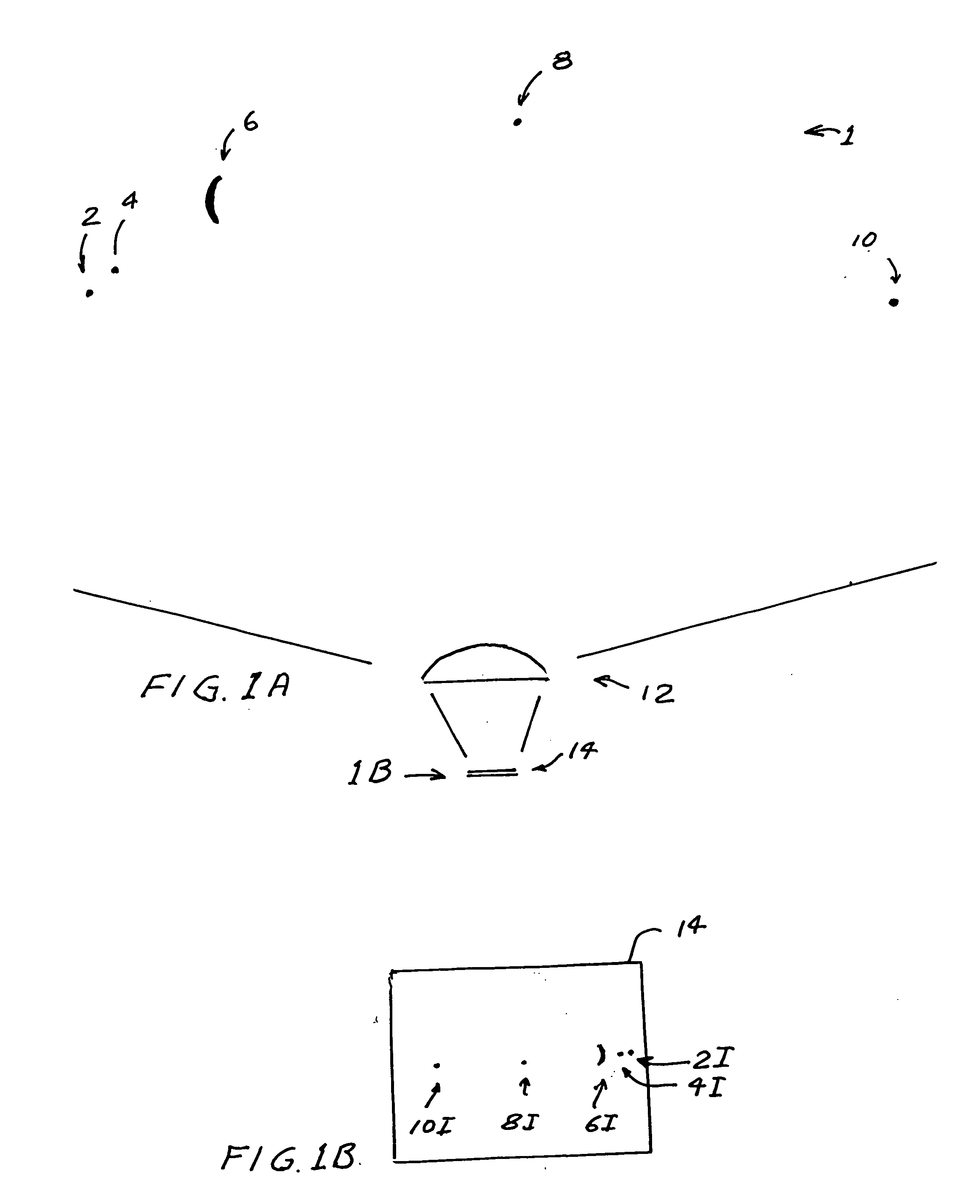
[0012] As shown in FIG. 1A about 170 degrees of a nighttime hemisphere 1 is viewed via a camera 18 with a fisheye lens 12 and ...

second preferred embodiment

Observation of Celestial Arcs

[0018] An alternate design uses the same wide angle lens and camera, but slightly different software. If the instrument is stationary for a period of time, for example a few minutes, then target identification is not required. The motion of any celestial target over a short period will describe an arc across the sky. The arcs that are directly North or South of the observer will be horizontal and parallel to the horizon, but travel in opposite directions. Arcs directly East or West will be vertical to some extent, depending on the observer's latitude. By calculating the arc's direction, the target does not need to be identified. This allows the instrument to calculate its orientation based on only a single unidentified star at night.


PUM


Abstract

A celestial compass. The celestial compass includes a camera with a wide angle lens suitable for viewing a large portion of the sky and a many-pixel sensor for collecting images of celestial objects such as stars, planets, the moon and the sun. The compass also includes a computer programmed with an (1) astronomical algorithm for providing the precise position of celestial objects based on precise input of time (date and time of day) and observation position (latitude and longitude), (2) celestial navigation software and (3) coordinate transformation software to correct distortion, convert pixel image data to astronomical coordinates and determine the instruments azimuth. The system includes provisions for the input of precise time and location information.

Description

[0001] The present invention claims the benefit of Provisional Patent Application Ser. No. 60 / 739,350, filed Nov. 23, 2005.BACKGROUND OF THE INVENTION [0002] The precise location of a target, viewed from an observation position on or near the surface of the earth can be made with the measurement of three coordinates; elevation (i.e. the direction of the vertical of the observation position, azimuth (i.e. the horizontal direction to the target, and range (i.e. the distance to the target). Elevation at the observation position can easily be found by using an inclinometer. Inclinometers with accuracies of about 10 micro-radians are available from suppliers such as Jewell Instruments with offices in Manchester, N.H. The cost of these inclinometers typically are in the range of about $2,000. Range can be determined with a laser rangefinder. Laser rangefinders with accuracies in the range of about 1 meter are available from suppliers such as Ratheon and the cost of these instruments is in...

Claims


Application Information

Patent Timeline
Patent Type & Authority Applications(United States)
IPC IPC(8): G09B27/00
CPCG09B27/00G01C17/34
Inventor BRUNS, DONALDSANDLER, DAVIDBELENKII, MIKHAIL
Owner TREX ENTERPRISES CORP
Why Eureka
Try Eureka