Laparoscopic surgical clamp and suturing methods

a laparoscopic and surgical technology, applied in the field of medical devices, can solve the problems of reducing the size of the surgical site, affecting the surgical operation, and limiting the ability of laparoscopic liver resection to be performed

Inactive Publication Date: 2007-05-24
CHU DAVID Z J
View PDF24 Cites 180 Cited by
  • Summary
  • Abstract
  • Description
  • Claims
  • Application Information

AI Technical Summary

Benefits of technology

[0011] The laparoscopic surgical clamp further includes a double hand assembly operatively connected to at least one of the first set and second set of double jaws such that the jaws may move between the opened and closed positions relative to the motion of the double hand assembly. The double handle assembly has a locking mechanism allowing ease of engagement of the first set and second set of double jaws between the opened and closed positions.

Problems solved by technology

The more centrally located liver nodules and masses present a unique challenge and most are resected using open surgical techniques.
With the introduction of minimally invasive surgical procedures in recent years, surgical sites have decreased in size, and obstruction by large, surgical clamps of the surgeon's field of visibility or access to other locations at the surgical site have become problematic.
Furthermore, while open liver resections have several techniques to control parenchymal bleeding from the liver, laparoscopic liver resections are primarily limited by the inability to control bleeding.
In addition, liver ligatures are difficult to apply by laparoscopic means.
Sutures of this size are difficult to introduce and maneuver within the minimally invasive body cavity.

Method used


Image

  • Laparoscopic surgical clamp and suturing methods
  • Laparoscopic surgical clamp and suturing methods
  • Laparoscopic surgical clamp and suturing methods

Examples


Embodiment Construction

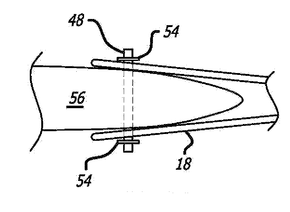
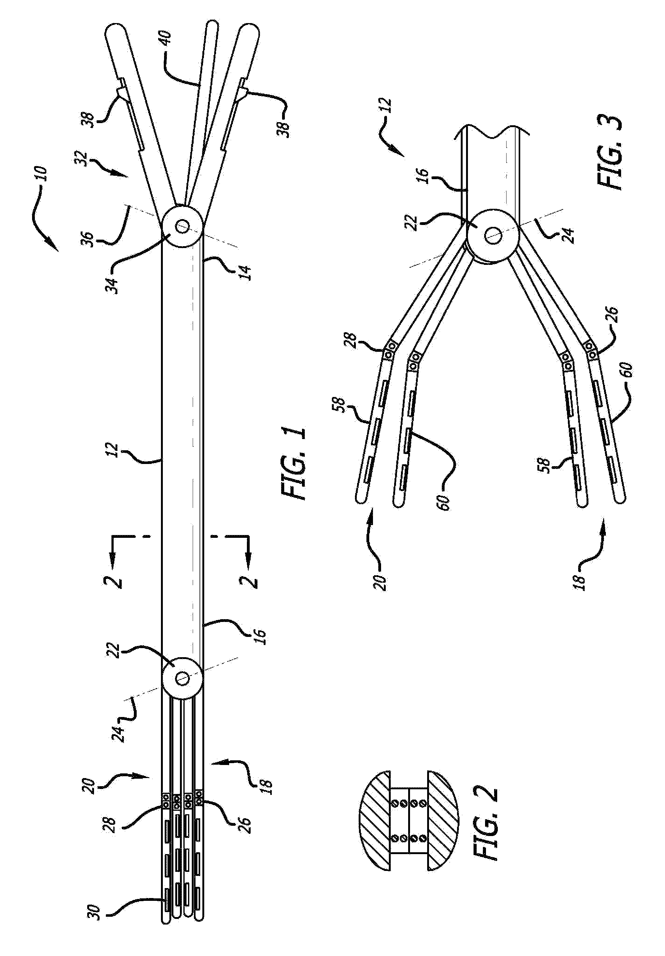
[0037] The laparoscopic surgical clamp 10 used in accordance with the methods of the present invention is generally illustrated in FIG. 1. The laparoscopic surgical clamp 10 is particularly configured to be applied to a patient's internal organs, including, but not limited to, the liver, lung, spleen and kidney, during minimally invasive surgical procedures. The laparoscopic surgical clamp 10 includes an elongated shaft 12 having a proximal end 14 and a distal end 16. First set and second set of double jaws 18, 20 are connected to the distal end 16 of the elongated shaft 12 by a pivot 22 and are pivotally moveable relative to one another about a rotational axis 24.

[0038] The laparoscopic surgical clamp has the capability of being manipulated into various positions as desired by the surgeon during the minimally invasive surgical procedure. In an opened position, the first set and second set of double jaws 18, 20 are separated and substantially parallel to one another. In a closed po...


PUM


Abstract

A method of occluding a patient's organ tissue during a minimally invasive surgical procedure is disclosed. The method includes providing a laparoscopic surgical clamp; passing distal end of surgical clamp into an opening of patient's body cavity; probing patient's tissue by moving first set and second set of double jaws of the surgical clamp between opened and closed positions; selecting tissue appropriate for being occluded with surgical clamp and suturing; clamping tissue with surgical clamp; passing at least one elongated suture into patient's body cavity with laparoscopic grasper; threading suture through a plurality of fenestration on at least one of upper portions of double jaws; puncturing patient's tissue with suture; threading suture through fenestration of at least one of the lower portions of double jaws; and clipping each end of suture on upper and lower portions of double jaws for securing the patient's tissue in a compressed position.

Description

BACKGROUND OF THE INVENTION [0001] 1. Field of the Invention [0002] The present invention relates to the field of medical devices, and more specifically to methods for occluding and suturing a patient's organ tissue using a laparoscopic surgical clamp in conjunction with sutures during minimally invasive surgical procedures. The laparoscopic surgical clamp is particularly beneficial in that it allows for resections of liver lesions of different sizes and anatomical locations and lesions in close proximity to the major liver vessels. A novel suturing method to complement this laparoscopic technique as well as other ligation techniques is disclosed and is ideal for liver and other solid organs in order to achieve hemostasis. [0003] 2. Description of the Prior Art [0004] Surgical clamps that use various types of clamping jaws and clamping configurations (i.e., curved, straight, and the like) are well known in the medical device art. In particular, large tissue clamps to accommodate sub...

Claims


Application Information

Patent Timeline
Patent Type & Authority Applications(United States)
IPC IPC(8): A61B17/00A61B17/08
CPCA61B17/0401A61B17/0469A61B17/0487A61B2017/0454A61B2017/0464A61B2017/0488A61B2017/303
Inventor CHU, DAVID Z. J.
Owner CHU DAVID Z J
Why Eureka
Try Eureka