Fluted sleeve hip prosthesis for modular stem

Active Publication Date: 2007-05-24
SMITH & NEPHEW INC
View PDF45 Cites 58 Cited by
  • Summary
  • Abstract
  • Description
  • Claims
  • Application Information

AI Technical Summary

Benefits of technology

[0027] The longitudinally extending bone engagement member provides for rotational and axial stability for the intramedullary implant. The longitudinally extending bone

Problems solved by technology

This is particularly an issue in revision surgeries, although it may also be a concern during a primary surgery.
Some surgeons using traditional, conical, tapered hip stems find it difficult to recreate the femoral neck height because the stem locks into place within the femoral canal too high or too low.
The primary factors resulting in stem placement uncertainty are the difficulty in reproducible reamer depth placement and variations in bone quality.
Some revision tapered hip stems offer modular necks of various heights to compensate for the difficulty, but offering modular necks as the sole solution may increase the complexity of the surgical procedure.
However, the biological enhancement coating in conjunction with the cylindrical shape of the implant may cause stress-shielding to the proximal bone due to the concentration of loading forces in the mid to distal portion of the stem.
The inefficient loading distribution likely causes bone loss proxima

Method used


Image

  • Fluted sleeve hip prosthesis for modular stem
  • Fluted sleeve hip prosthesis for modular stem
  • Fluted sleeve hip prosthesis for modular stem

Examples


Example

[0049] The following description of the preferred embodiment(s) is merely exemplary in nature and is in no way intended to limit the invention, its application, or uses.

[0050] Intramedullary stems developed for enhanced distal stabilization are often formed as cylindrical stems, grit-blasted tapered stems, or long stems (which are often necessarily bowed due to their use and the patient's anatomy.) All of these stems have drawbacks. For example, most bowed stems limit the surgeon's ability to orient the stem; if it is not modular, the stem can only be implanted such that the bow corresponds to the natural curve of the patient's bone. Accordingly, the present invention provides an alternate to current stems, while still providing enhanced distal fixation, modularity options, enhanced stabilization, and flexibility.

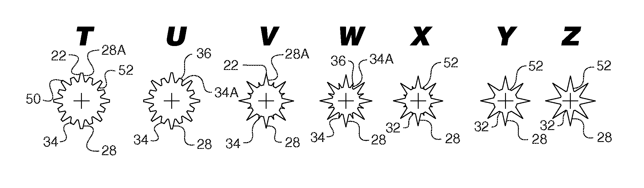
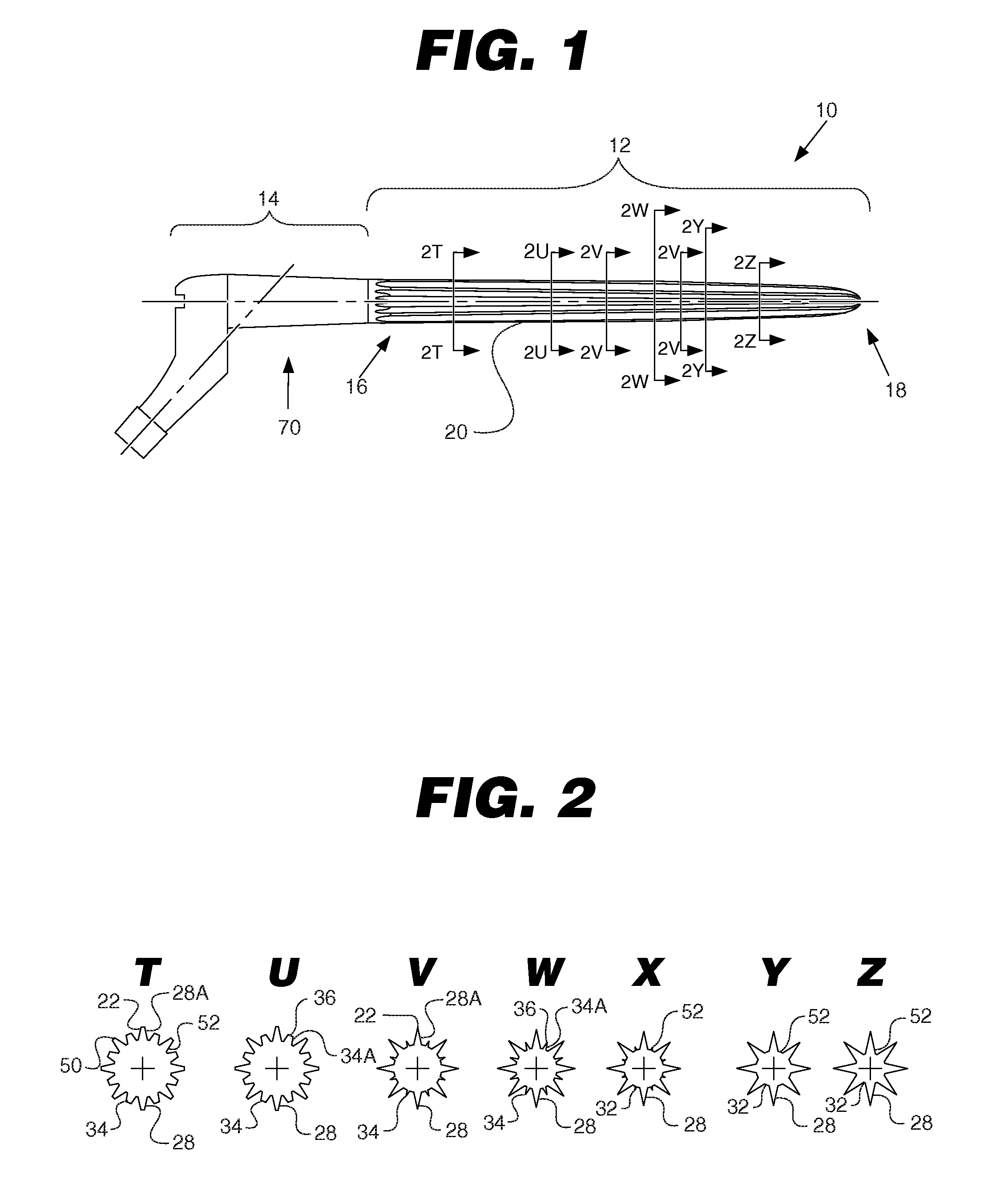
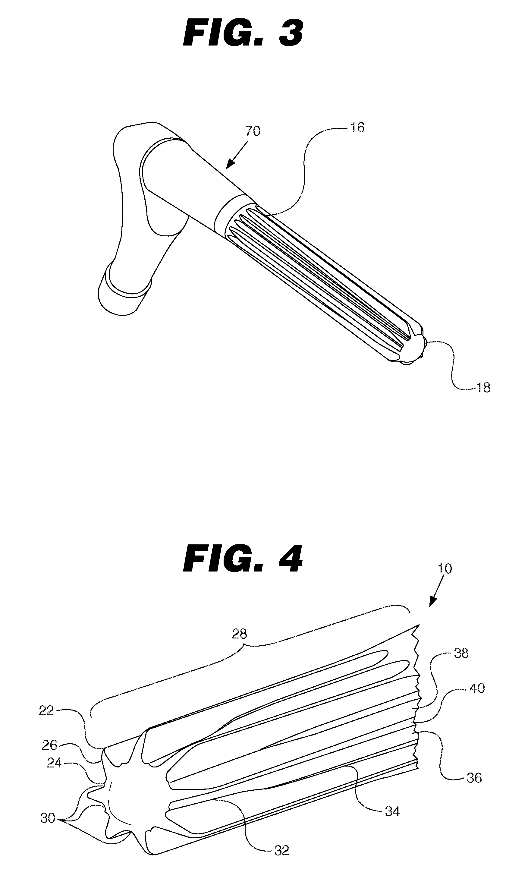
[0051] As shown in FIG. 1, intramedullary implant 10 has a shaft 12 with a longitudinal length and an upper stem portion 14. The intramedullary implant 10 also may be ref...


PUM

PropertyMeasurementUnit
Lengthaaaaaaaaaa
Shapeaaaaaaaaaa
Widthaaaaaaaaaa

Abstract

An intramedullary implant for mounting within an intramedullary canal of a bone is disclosed. The intramedullary implant includes a lower stem portion, an upper stem portion, and a modular sleeve body. The modular sleeve body is connected to one of the lower stem portion or the upper stem portion. The sleeve body includes an inner portion that covers at least a segment of the upper stem portion and has one or more longitudinally extending bone engagement members for engagement with the bone.

Description

CROSS-REFERENCE TO RELATED APPLICATIONS [0001] This application is a continuation-in-part of U.S. patent application Ser. No. 11 / 139,926 filed on May 27, 2005, which claimed priority to U.S. Provisional Patent Application No. 60 / 575,636 filed on May 28, 2004 and U.S. Provisional Patent Application No. 60 / 655,129 filed on Feb. 22, 2005. This application claims the benefit of U.S. Provisional Application No. 60 / 761,056 filed Jan. 20, 2006. The disclosure of each prior application is incorporated by reference in its entirety.BACKGROUND OF THE INVENTION [0002] 1. Field of the Invention [0003] The present invention relates, in general, to intramedullary implants and stems, and particularly hip stems, that are provided to replace worn joints. [0004] 2. Related Art [0005] Artificial implants, including hip joints, shoulder joints, and knee joints, are widely used in orthopedic surgery. Artificial hip and shoulder joints are generally ball and socket joints, designed to match as closely as ...

Claims


Application Information

Patent Timeline
IPC IPC(8): A61F2/36A61F2/28
CPCA61F2/30734A61F2/30767A61F2/30771A61F2/36A61F2/3662A61F2/367A61F2/3676A61F2002/30034A61F2002/30062A61F2002/30156A61F2002/30171A61F2002/3021A61F2002/30217A61F2002/30235A61F2002/30322A61F2002/30326A61F2002/30327A61F2002/30332A61F2002/30354A61F2002/30383A61F2002/30387A61F2002/30535A61F2002/30604A61F2002/30616A61F2002/30677A61F2002/30738A61F2002/3082A61F2002/30827A61F2002/30848A61F2002/30879A61F2002/30884A61F2002/30891A61F2002/30906A61F2002/30925A61F2002/30968A61F2002/30971A61F2002/3625A61F2002/365A61F2002/3664A61F2002/3696A61F2002/4631A61F2210/0004A61F2220/0025A61F2220/0033A61F2230/0023A61F2230/005A61F2230/0067A61F2230/0069A61F2250/0026A61F2250/0031A61F2250/0037A61F2250/0039A61F2250/0058A61F2310/00011A61F2310/00017A61F2310/00023A61F2310/00179A61F2310/00796A61F2002/30032A61F2002/30878A61F2002/30845A61F2002/30594
Inventor BERGIN, ALISHA W.JONES, JERRY L.KELMAN, DAVID C.LAMBERT, RONANT D.MCLEAN, TERRY W.
Owner SMITH & NEPHEW INC
Why Eureka
Try Eureka