Equipment control apparatus, remote controller, equipment, equipment control method, and equipment control program product

a technology for remote controllers and equipment, applied in the direction of instruments, computing, electric digital data processing, etc., can solve the problems of difficult to reduce impede the reduction of the suffer the difficulty of achieving a smaller size of the remote control apparatus, so as to achieve the effect of less likely to malfunction and easy to reduce the siz

Inactive Publication Date: 2007-05-24
SHARP KK
View PDF0 Cites 25 Cited by
  • Summary
  • Abstract
  • Description
  • Claims
  • Application Information

AI Technical Summary

Benefits of technology

[0009] The present invention was made to solve the above-described problems. An object of the present invention is to provide an equipment control apparatus ...

Problems solved by technology

The invention disclosed in Japanese Patent Laying-Open No. 06-153017, however, suffers difficulty in achieving a smaller size of the remote control apparatus.
Presence of the monitor impedes reduction in size of the remote control apparatus, which makes it difficult to make smaller the remote control apparatus.
In addition, according to the invention disclosed in Japanese Patent Laying...

Method used


Image

  • Equipment control apparatus, remote controller, equipment, equipment control method, and equipment control program product
  • Equipment control apparatus, remote controller, equipment, equipment control method, and equipment control program product
  • Equipment control apparatus, remote controller, equipment, equipment control method, and equipment control program product

Examples


first embodiment

[0043] An equipment control apparatus according to a first embodiment of the present invention will be described hereinafter.

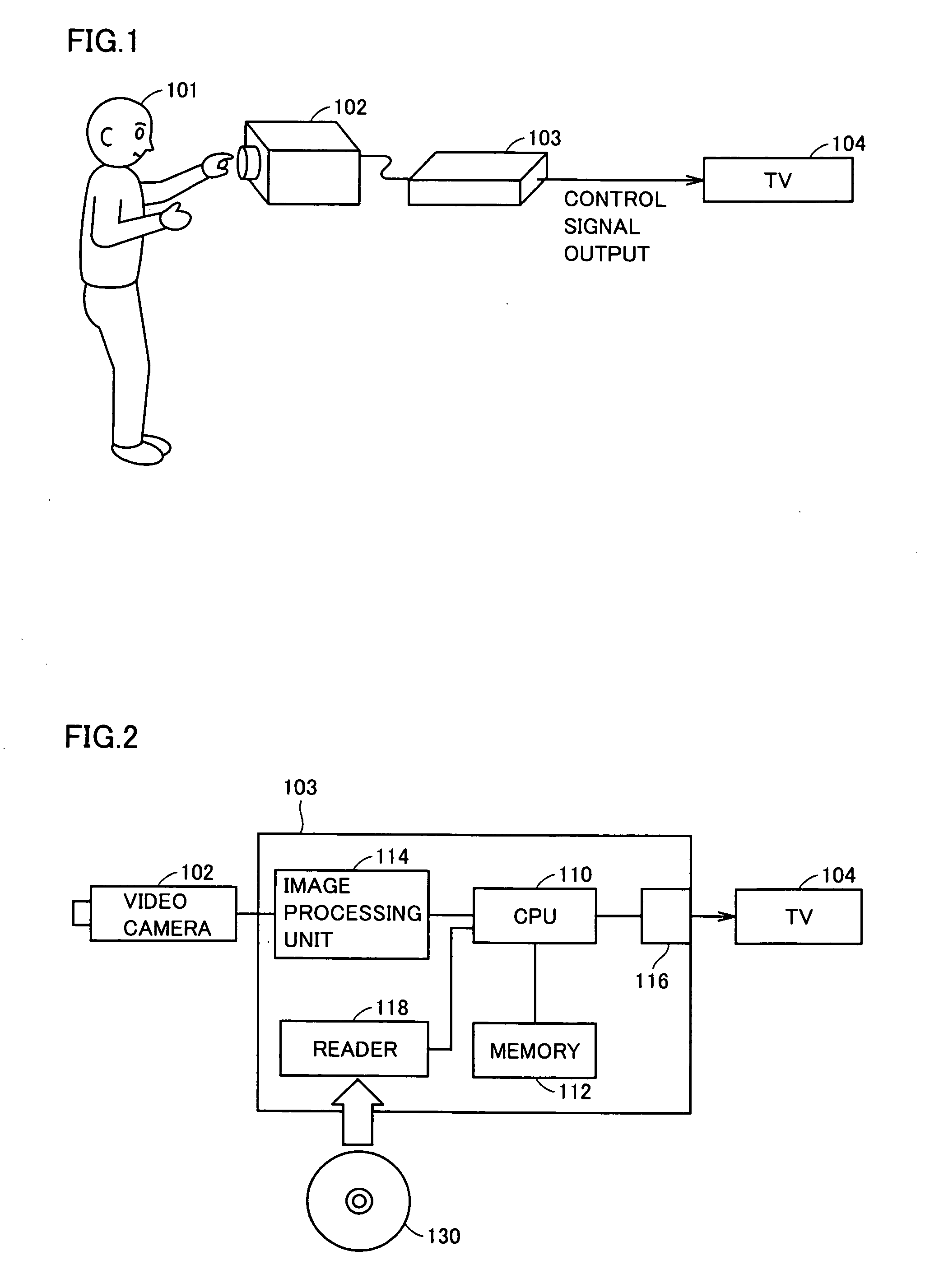
[0044]FIG. 1 is a conceptual diagram illustrating a configuration of the equipment control apparatus and a method of using the same according to the present embodiment.

[0045]FIG. 2 is a control block diagram of the equipment control apparatus according to the present embodiment. Referring to FIGS. 1 and 2, the equipment control apparatus includes a video camera 102 and a main apparatus 103. Video camera 102 is an apparatus that picks up an image of a hand or the like of a user 101. In the present embodiment, video camera 102 is implemented as a color camera equipped with a unit for image pick-up and employing a lens different from a wide-angle lens. Whether a lens may be mounted on video camera 102 or not is determined based on whether the entire image pick-up area is covered by a hand or the like when user 101 holds the hand or the like at a position severa...

second embodiment

[0069] An equipment control apparatus according to a second embodiment of the present invention will be described hereinafter.

[0070] The equipment control apparatus according to the present embodiment is the same as that in the first embodiment, and the function thereof is also the same. Therefore, detailed description thereof will not be repeated.

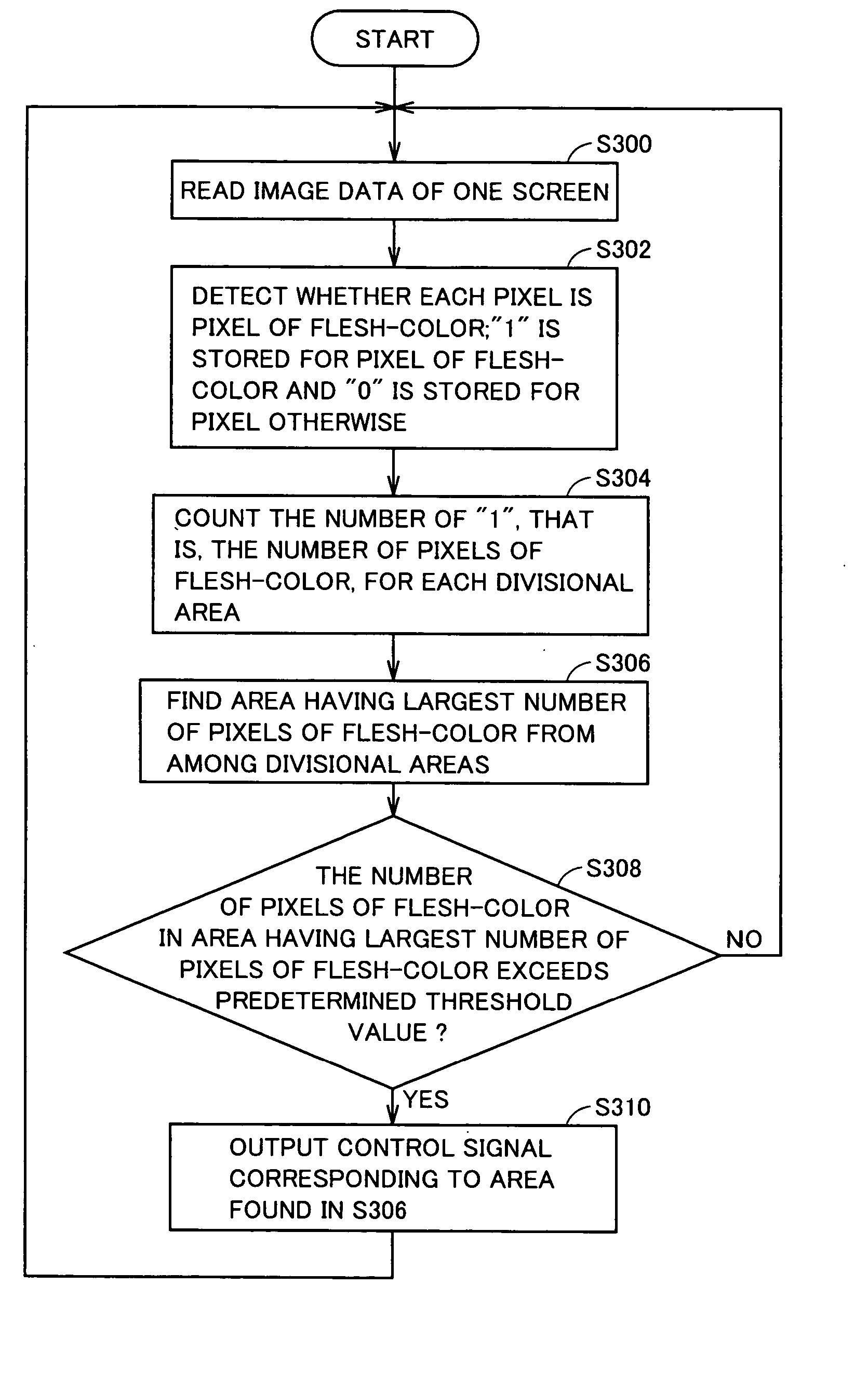
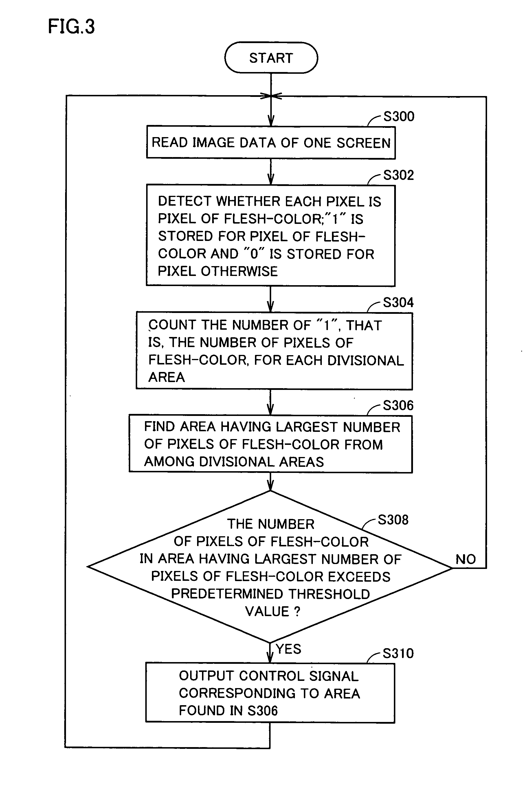
[0071] Referring to FIG. 7, the program executed in the equipment control apparatus carries out the following control for output of a control signal. It is noted that the processing in the flowchart in FIG. 7 that has been shown in FIG. 3 described previously is given the same step number, and the processing is also the same. Therefore, detailed description thereof will not be repeated.

[0072] In S320, CPU 110 sets the value of the counter to “0”.

[0073] In S322, CPU 110 determines whether the specific number of the area having the largest specific number exceeds a predetermined threshold value. If it is determined that the predetermined...

third embodiment

[0080] An equipment control apparatus according to a third embodiment of the present invention will be described hereinafter.

[0081] The hardware configuration of the equipment control apparatus according to the present embodiment is the same as that in the first embodiment described previously, and the function thereof is also the same. Therefore, detailed description thereof will not be repeated.

[0082] Referring to FIG. 8, the program executed in the equipment control apparatus carries out the following control for output of a control signal. It is noted that the processing in the flowchart in FIG. 8 that has been shown in FIG. 3 described previously is given the same step number, and the processing is also the same. Therefore, detailed description thereof will not be repeated.

[0083] In S330, CPU 110 causes memory 112 to store image data read from video camera 102, in a certain area thereof. By storing the image data, memory 112 stores a plurality of images. The plurality of ima...


PUM


Abstract

An equipment control apparatus readily made smaller in size and less likely to malfunction is configured as follows. The equipment control apparatus includes a video camera, a CPU, and a terminal. The video camera picks up an image. The CPU determines whether a color of a pixel forming the image picked up by the video camera represents a color of skin of a human body, counts the specific number indicating the number of pixels of which color represents the color of skin of the human body for an area representing at least a part of the image, and determines whether the specific number exceeds a threshold value. A memory stores the specific number in association with the area. The terminal outputs a control signal of a type corresponding to the area, if the specific number exceeds the threshold value.

Description

[0001] This nonprovisional application is based on Japanese Patent Application No. 2005-297876 filed with the Japan Patent Office on Oct. 12, 2005, the entire contents of which are hereby incorporated by reference. FIELD OF THE INVENTION [0002] The present invention relates to an equipment control apparatus, a remote controller, equipment, an equipment control method, and an equipment control program product, and particularly to an equipment control apparatus controlling every equipment in a non-contact manner by converting data, a remote controller, equipment, an equipment control method, and an equipment control program product. DESCRIPTION OF THE BACKGROUND ART [0003] Japanese Patent Laying-Open No. 06-153017 discloses a remote control apparatus including a monitor, an infrared camera detecting an image of a human body, and a CPU (Central Processing Unit) for controlling the display of the image of the human body detected by the infrared camera and superimposed control item areas...

Claims


Application Information

Patent Timeline
Owner SHARP KK
Why Eureka
Try Eureka