
Inflatable incontinence bed pad

Inactive Publication Date: 2007-05-31
BATES JASON
View PDF25 Cites 29 Cited by
  • Summary
  • Abstract
  • Description
  • Claims
  • Application Information

AI Technical Summary

Benefits of technology

[0025] The air bladder may be sealed in various zones and these zones may be inflated or deflated over time to tilt the user or offer alternating pressure zones. The air bladder may have small holes to release air for the purposes of protecting the pad and the user from excessive air pressure or for patient benefits such as low air loss moisture wicking.

Problems solved by technology

The existing pads do not provide any additional support for the patient on a bed.
Patients typically lay in the wet absorbent pads after urinating, increasing the likelihood of skin maceration (over-hydration) and infection of wounds.
Inflating and deflating areas of the pad may push waste away from the person.
The large receptacle openings for drainage may reduce the area for a patient to lay on, thereby increasing pressure areas.
These systems cannot be used as a transfer pad or as a sling for use with a patient lift.
It is not possible to machine wash or to machine dry these devices.
These devices do not work in conjunction with a standard absorbent incontinence pad.
These devices require more resources to build and would likely be more expensive.
Those who are bed-bound for extended periods can suffer from bedsores.
People can seek medical attention, and then find themselves unable to be discharged due to bedsores, even with the original ailment resolved.
Body wastes collected on an incontinence bed pad in the vicinity of a bed sore can cause infection to wounds.
The vinyl material holds moisture in which can cause skin maceration.
Reduced air circulation and heat build-up on the patient's skin may also be problems.
Low air loss and alternating pressure mattresses are cumbersome to store, move, and install.
They are also very difficult to clean.
If even one air cell deflates it can create discomfort for the patient and the care providers.
It is not practical for care providers to turn a patient every 15 minutes.
Care providers who turn patients and transfer patients have a poor record for lower back injuries.
They are very expensive, heavy, and have many parts that can fail.
This can disrupt activities such as eating or watching TV.
This is unhelpful to the prevention or treatment of bed wounds and can scare a patient.
Caregivers are often busy during a power outage and cannot attend as well to a patient's safety and comfort.

Method used


Image

  • Inflatable incontinence bed pad
  • Inflatable incontinence bed pad
  • Inflatable incontinence bed pad

Examples


Embodiment Construction

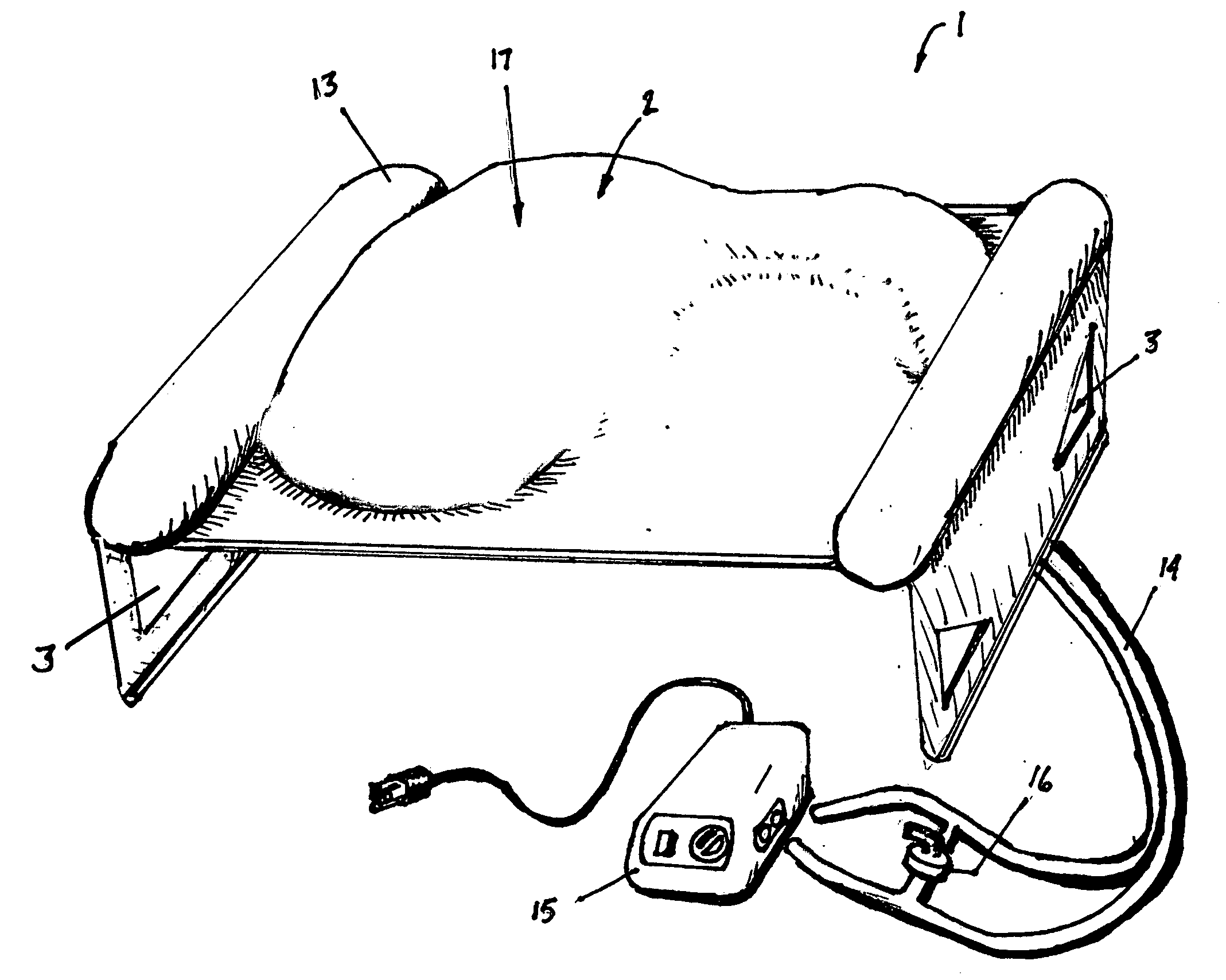
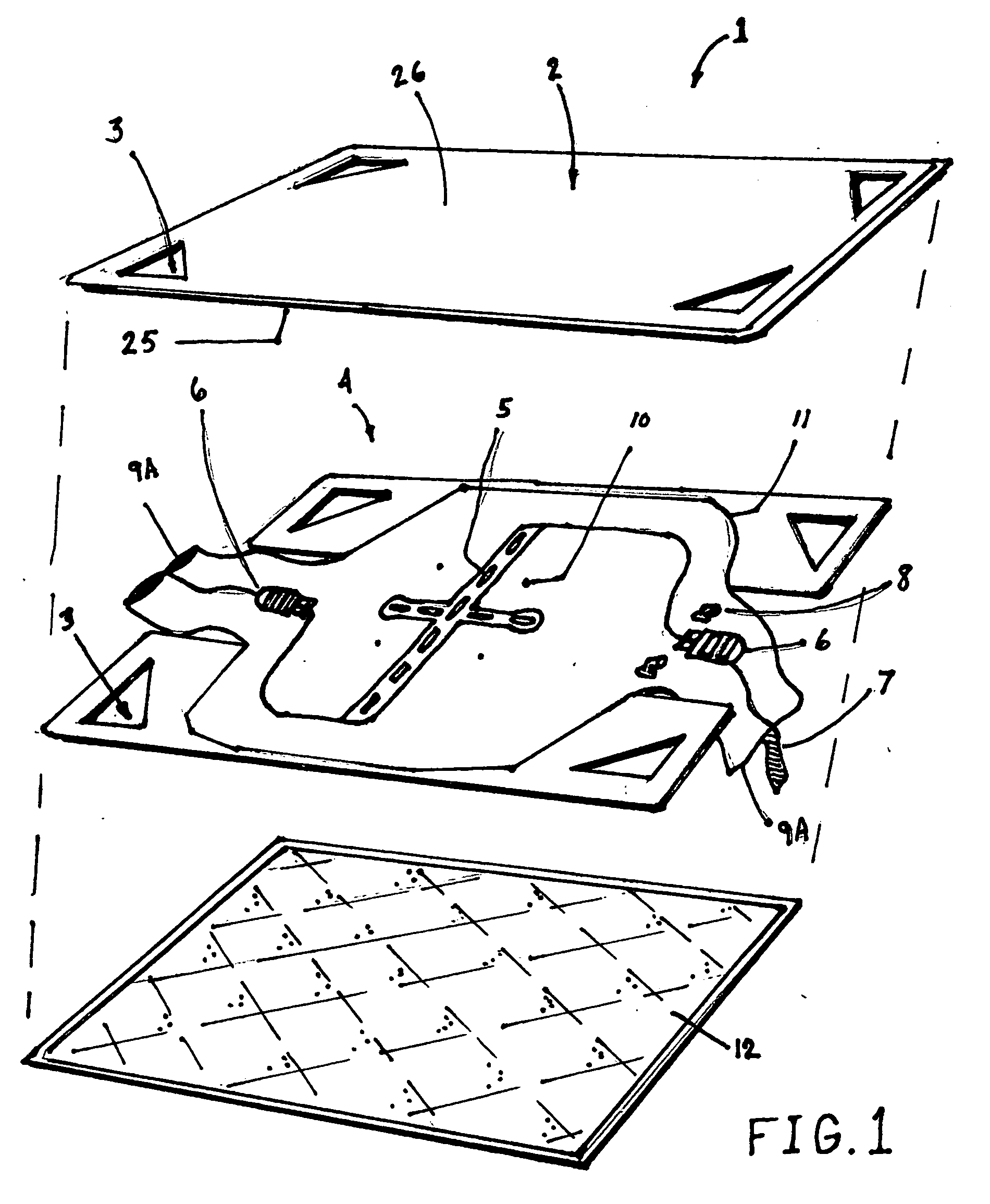
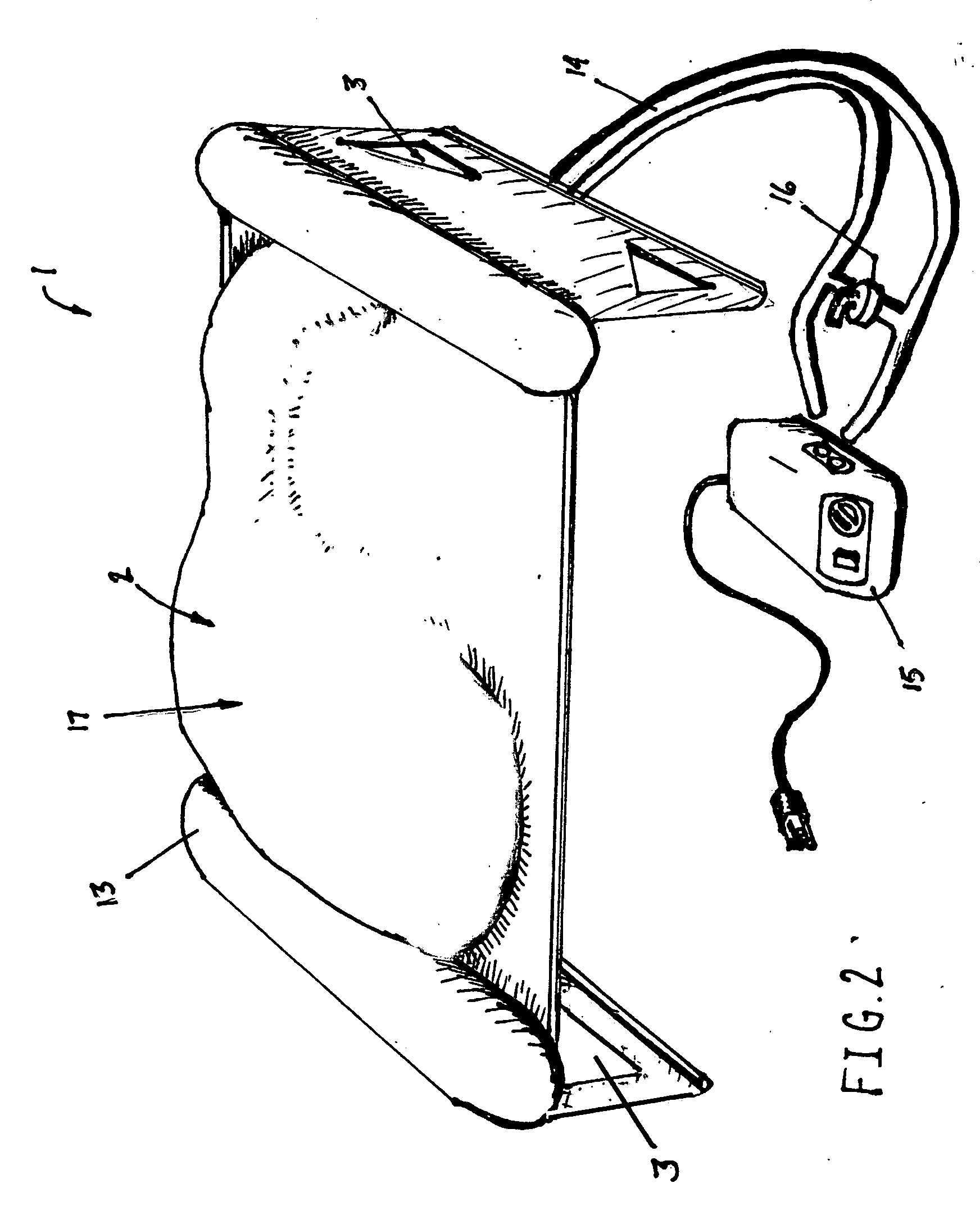
[0036]FIG. 1 shows an exploded view of three main components of the preferred embodiment of the inflatable incontinence pad 1: a cover 2, an inflatable pad 4, and a standard absorbent incontinence pad 12.

[0037] A cover 2 may be made of a low friction top layer 26 and a layer underneath 25. The top layer may be made of nylon or some other suitable material. The layer beneath the top layer may be made of Dacron, poly-fill, or other suitable material. Preferred materials may disperse air from low air loss emitted by the inflatable layer. They will allow fluids to drain downward. They may not compress enough to block air circulation under pressure. The cover 2 may hold solid waste but allow fluids to pass through, like a filter. This feature is for keeping the patient on top of the cover dry. The top layer 26 may be perforated. The cover may have holes to form handles 3 that may combine with holes in the inflatable layer 4 to form handles 3. The cover 2 may be free to move atop of the ...


PUM


Abstract

An incontinence bed pad comprised of one or more inflatable pads and one or more absorbent pads for use under a patient on a bed. The inflatable incontinence bed pad serves to spread pressure over an increased area for the patient to prevent or treat bed wounds. The inflatable pad may channel or drain fluids such as urine into the absorbent pad below, keeping the surface and patient dry. Alternately, the absorbent pad may be placed above the inflatable pad to reduce cleaning work. The one or more air bladders are inflatable through one or more ports. The ports pass air from one or more manual or powered air pumps to the one or more air bladders. Making an incontinence pad of an inflatable nature offers advantages not available in the prior art. The inflation and deflation of distinct sealed chambers or zones within the inflatable pad may tilt a patient's hips to the right and to the left periodically. The pad may inflate in a static position. The pad may inflate and deflate zoned areas to alternate pressure areas of the patient. Inflating and deflating areas of the pad may push waste away from the person. The inflated pad may leak air to wick moisture and heat from a patient. Handles may be integrated to the inflatable incontinence bed pad for transferring the patient on and off the bed and to other places. Straps compatible with a patient lift system may be integrated. This could reduce work and injury to care providers, as well as reducing disruption to the patient. Side rails may be integrated for safety.

Description

BACKGROUND OF THE INVENTION [0001] (i) Field of the Invention [0002] This invention relates in general to an inflatable incontinence bed pad, in particular, the invention relates to an incontinence bed pad utilized for bed wound prevention and treatment as well as adding features to benefit care providers. [0003] (ii) Description of the Related Art [0004] This invention relates to incontinence pads used on beds. Incontinence pads in use today are typically made of cotton or some absorbent material. In many cases two or more may be used under a patient in order to soak up bodily fluids such as urine and to separate the waste from the bed. The existing pads do not provide any additional support for the patient on a bed. [0005] By making an incontinence pad of inflatable form, the incontinence pad goes from being two-dimensional to being three-dimensional. Since a person's body has three-dimensional contours, it follows that the inflatable bed pad can offer a person support over a larg...

Claims


Application Information

Patent Timeline
IPC IPC(8): A61G9/00A47C27/10
CPCA61G7/02A61G7/05776A61G7/1021A61G7/1051A61G2200/32
Inventor BATES, JASON
Owner BATES JASON
Learn More