Nozzle assembly for rocket and ramjet applications

a technology for ramjets and nozzles, which is applied in the direction of jet propulsion plants, rocket engine plants, machines/engines, etc., can solve the problems of difficult and/or expensive manufacturing, unreliable operation, and complicated construction, and achieve the effect of reducing the obstruction of gas flow

Inactive Publication Date: 2007-05-31
AEROJET ROCKETDYNE INC
View PDF18 Cites 19 Cited by
  • Summary
  • Abstract
  • Description
  • Claims
  • Application Information

AI Technical Summary

Benefits of technology

[0025] The vane members preferably have a streamlined shape so as to minimize the obstruction to gas flow through the nozzle housing when the vane members are in the fully open, substantially parallel positions. The vane members may be constructed of any suitable high temperature-resistant material.

Problems solved by technology

They are complicated in construction;
They are difficult and / or expensive to manufacture;
They are unreliable in operation;
The operating mechanisms are exposed to hot exhaust gases and thus are subject to deterioration;

Method used


Image

  • Nozzle assembly for rocket and ramjet applications
  • Nozzle assembly for rocket and ramjet applications
  • Nozzle assembly for rocket and ramjet applications

Examples


Embodiment Construction

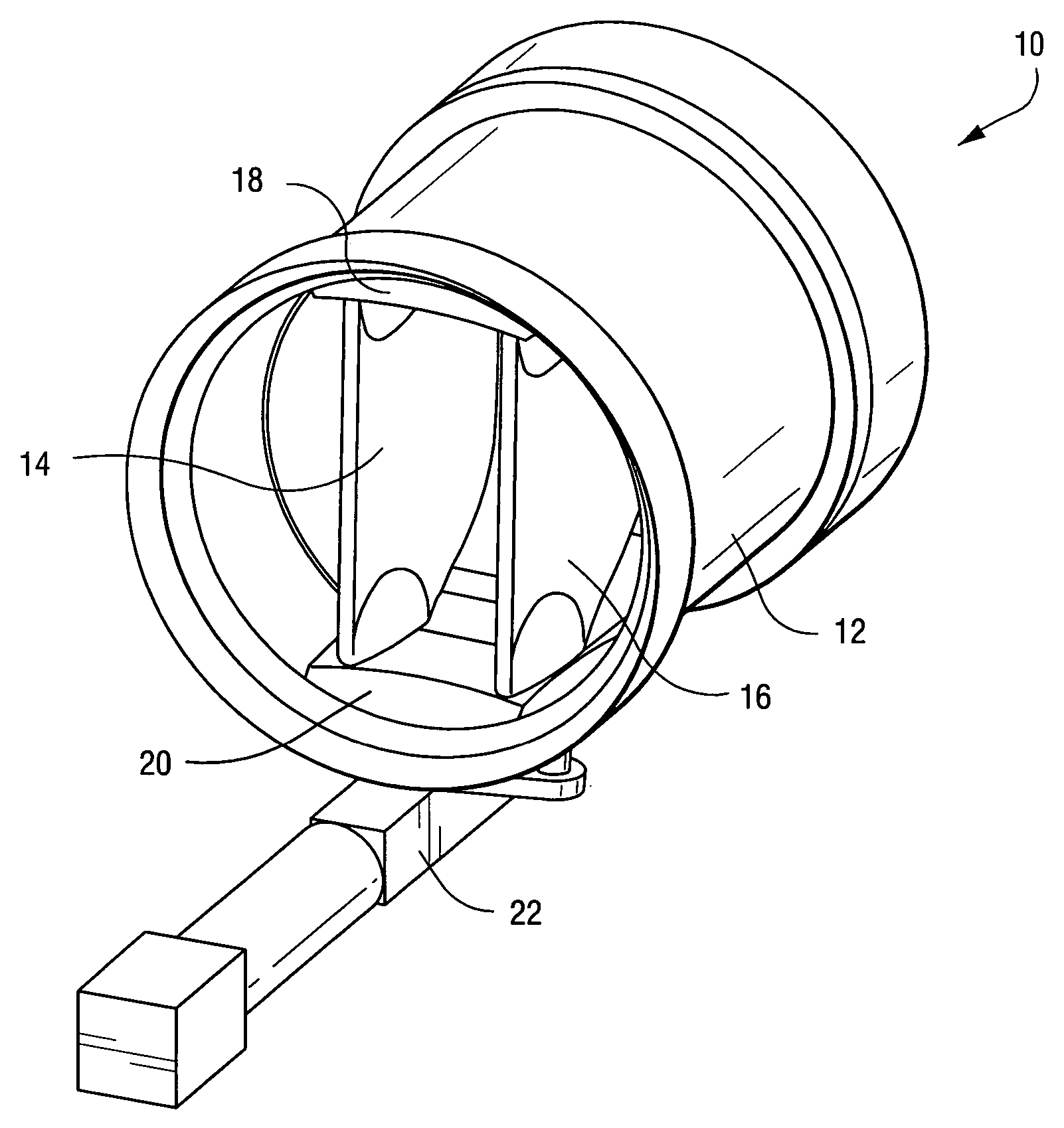
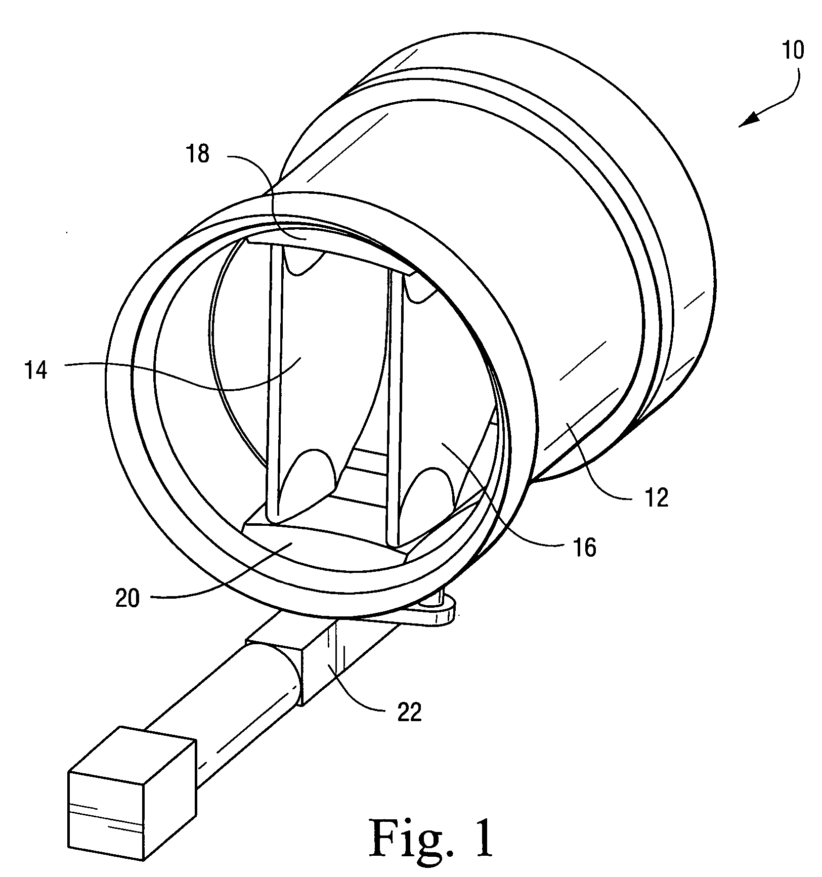
[0031] As shown in FIG. 1, the nozzle assembly 10 of the present invention generally comprises a nozzle housing 12 that is constructed to be secured at its forward end in any suitable manner to the housing of a rocket, ramjet or the like (not shown). The nozzle housing 12 may be of any suitable shape, such as cylindrical, and may be made of any suitable high temperature-resistant material.

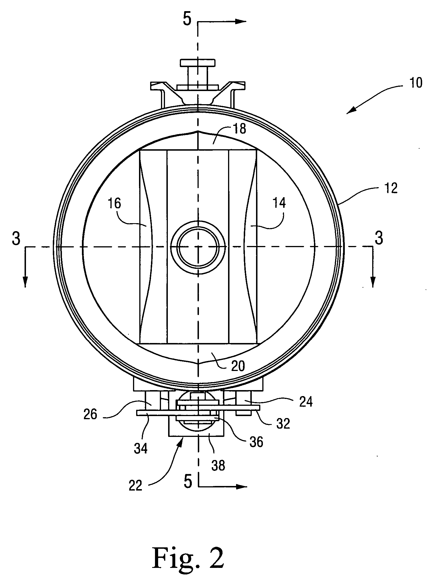
[0032] A pair of vane members 14,16 are pivotally mounted on the nozzle housing 12 and extend vertically or transversely between upper and lower platform portions 18, 20 on the nozzle housing 12. When in the fully open position shown in FIG. 1, the vane members 14, 16 extend in substantially parallel relation rearwardly or longitudinally through the nozzle housing 12.

[0033] An operating mechanism 22 of any suitable construction is connected in any suitable manner to the vane members 14, 16 to pivot them simultaneously or separately for varying the throat area of the nozzle housing 12 for thrust c...


PUM


Abstract

A nozzle assembly for thrust or thrust vector control of a rocket or ramjet, comprising an elongated nozzle housing and a pair of vane members mounted for pivotal movement within a central portion of the nozzle housing. The vane members extend vertically or transversely between the upper and lower portions of the nozzle housing near the forward portion thereof, and extend longitudinally in the nozzle housing from the forward end portion thereof to a point near the rear end portion thereof. The vane members are pivotable about axes disposed between the forward and rear ends thereof, and are movable between an open position wherein they are in substantially parallel relation and a closed position wherein their forward ends are in engagement with each other and their rear ends are in engagement with the adjacent inner surface of the nozzle housing. An operating mechanism is operatively connected to the vane members to move them simultaneously or individually between the open and closed positions for thrust control or thrust vector control.

Description

BACKGROUND OF THE INVENTION [0001] 1. Field of the Invention [0002] The present invention relates to a nozzle assembly for a rocket and / or ramjet which is constructed to effect large changes in the nozzle throat area with minimal actuation forces and component mass. [0003] 2. Description of Related Art [0004] Many different types of constructions and techniques are in the prior art for controlling the throat area in a nozzle assembly for rocket and / or ramjet applications to effect thrust and thrust vectoring control. Illustrative examples of such constructions and techniques are set forth in the patents described hereinafter. [0005] U.S. Pat. No. 3,570,247 discloses a jet nozzle having a center body provided with flaps 19 that are movable to divert the flow of gases for thrust-spoiling or thrust-reversing. [0006] U.S. Pat. No. 4,753,392 discloses a gas turbine engine exhaust nozzle including a pair of spaced-apart converging flaps which are rotatable about their respective axes to b...

Claims


Application Information

Patent Timeline
Patent Type & Authority Applications(United States)
IPC IPC(8): F02K1/00
CPCF02K1/002F02K1/1207F02K9/90F05D2240/12
Inventor MCALLISTER, ANDREW C.DOMBROWSKI, DANIEL C.
Owner AEROJET ROCKETDYNE INC
Why Eureka
Try Eureka