Heat exchanger
- Summary
- Abstract
- Description
- Claims
- Application Information
AI Technical Summary
Benefits of technology
Problems solved by technology
Method used
Image
Examples
Embodiment Construction
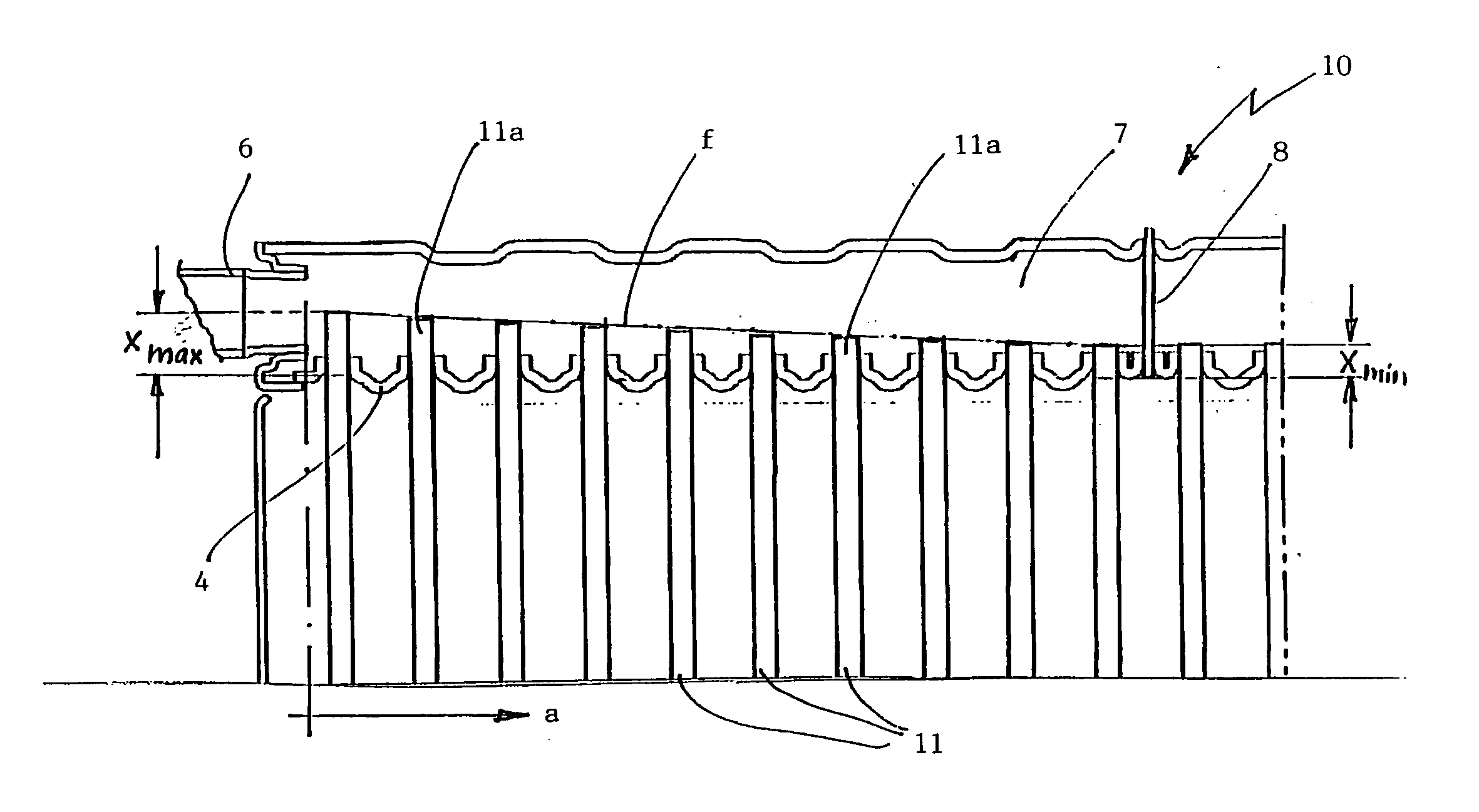
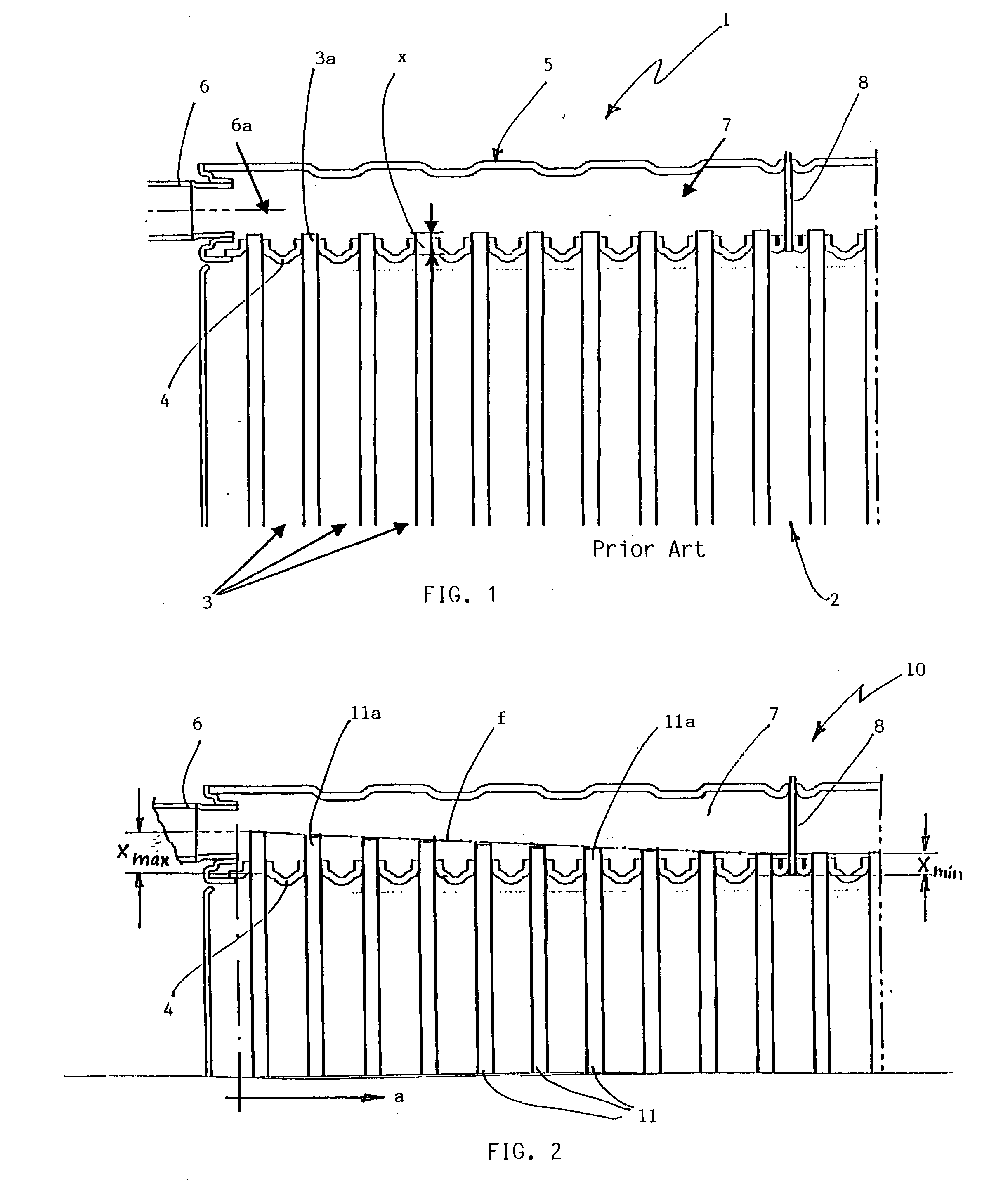
[0012]FIG. 1 is a cutaway view of an evaporator 1 as it is known from the prior art, for example, from U.S. Pat. No. 6,449,979 or from international patent publication WO 2005 / 047800 A1. The evaporator 1 includes a block 2 of flat tubes 3. Ribs (not shown) are mounted between these tubes over which air flows. The tubes 3 have tube ends 3a which are inserted into a tube base 4. The tube base 4 is part of a collector 5 which has an injection tube 6 mounted at an end face and through which refrigerant is supplied to the evaporator 1. The axis of the injection tube 6 is identified by reference numeral 6a and this axis corresponds to the injection direction of the refrigerant. The collector 5 includes an inlet chamber 7 which is partitioned off relative to a neighboring chamber by a partition wall 8. The refrigerant reaches the inlet chamber 7 via the injection tube 6 and distributes from there to the tubes 3. The refrigerant then flows from top to bottom in the drawing, that is, in a di...
PUM
 Abstract
Description
Claims
Application Information
 - R&D
- Intellectual Property
- Life Sciences
- Materials
- Tech Scout
- Unparalleled Data Quality
- Higher Quality Content
- 60% Fewer Hallucinations
Browse by: Latest US Patents, China's latest patents, Technical Efficacy Thesaurus, Application Domain, Technology Topic, Popular Technical Reports.
© 2025 PatSnap. All rights reserved.Legal|Privacy policy|Modern Slavery Act Transparency Statement|Sitemap|About US| Contact US: help@patsnap.com


