Mirrored arc conducting pair

a technology of conducting pair and mirrored arc, which is applied in the direction of insulated conductors, cables, conductors, etc., can solve the problems of complex structure, increased cost, size, weight, and complexity of shields, and can easily be added over twisted pairs at additional cost, size, weight, and complexity, and achieve the effect of creating the same mirrored arc geometry

Inactive Publication Date: 2007-05-31
RGB SYST INC
View PDF4 Cites 3 Cited by
  • Summary
  • Abstract
  • Description
  • Claims
  • Application Information

AI Technical Summary

Benefits of technology

[0015] In one or more embodiments, each arc-shaped conductor may be constructed from a group of separate bare metal conductors (e.g. cylindrically shaped conductors) which are placed side by side in intimate contact so as to effectively create the same mirrored arc geometry.

Problems solved by technology

From an electrical point-of-view, the basic twisted pair is not shielded (i.e. UTP) and is susceptible to outside interference, crosstalk from other pairs, etc.
A shield can, and often is, added over the twisted pairs at additional cost, size, weight, and complexity.
The different twist rates contribute to lowered crosstalk but also contribute to skew (i.e. delay) between the conductor pairs because of the difference in length incident to the different twist rates.
However, the data networks and many analog applications utilizing twisted pair cable put new demands on twisted pair cable construction.

Method used


Image

  • Mirrored arc conducting pair
  • Mirrored arc conducting pair
  • Mirrored arc conducting pair

Examples


Embodiment Construction

[0026] The invention discloses a conductor pair for signal transmission, and method for making same. In the following description, numerous specific details are set forth to provide a more thorough description of the present invention. It will be apparent, however, to one skilled in the art, that the present invention may be practiced without these specific details. In other instances, well known features have not been described in detail so as not to obscure the present invention.

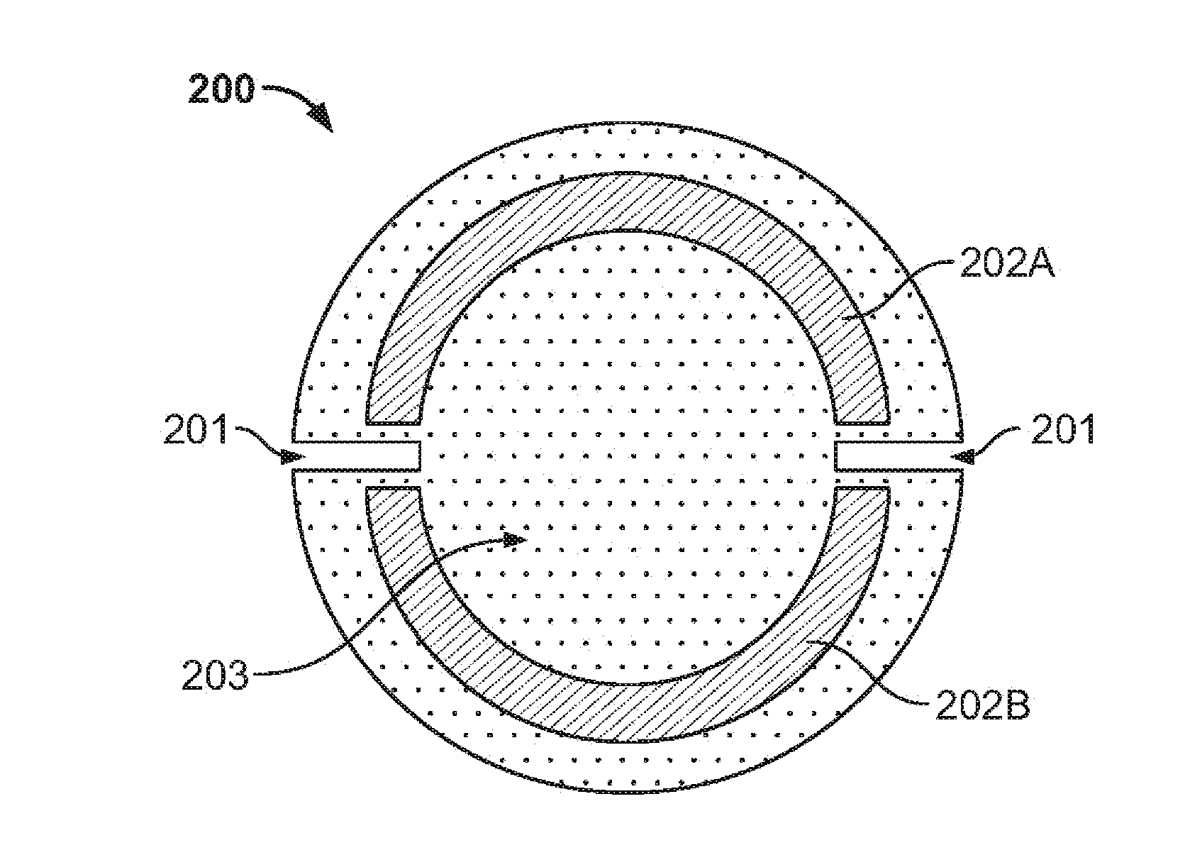
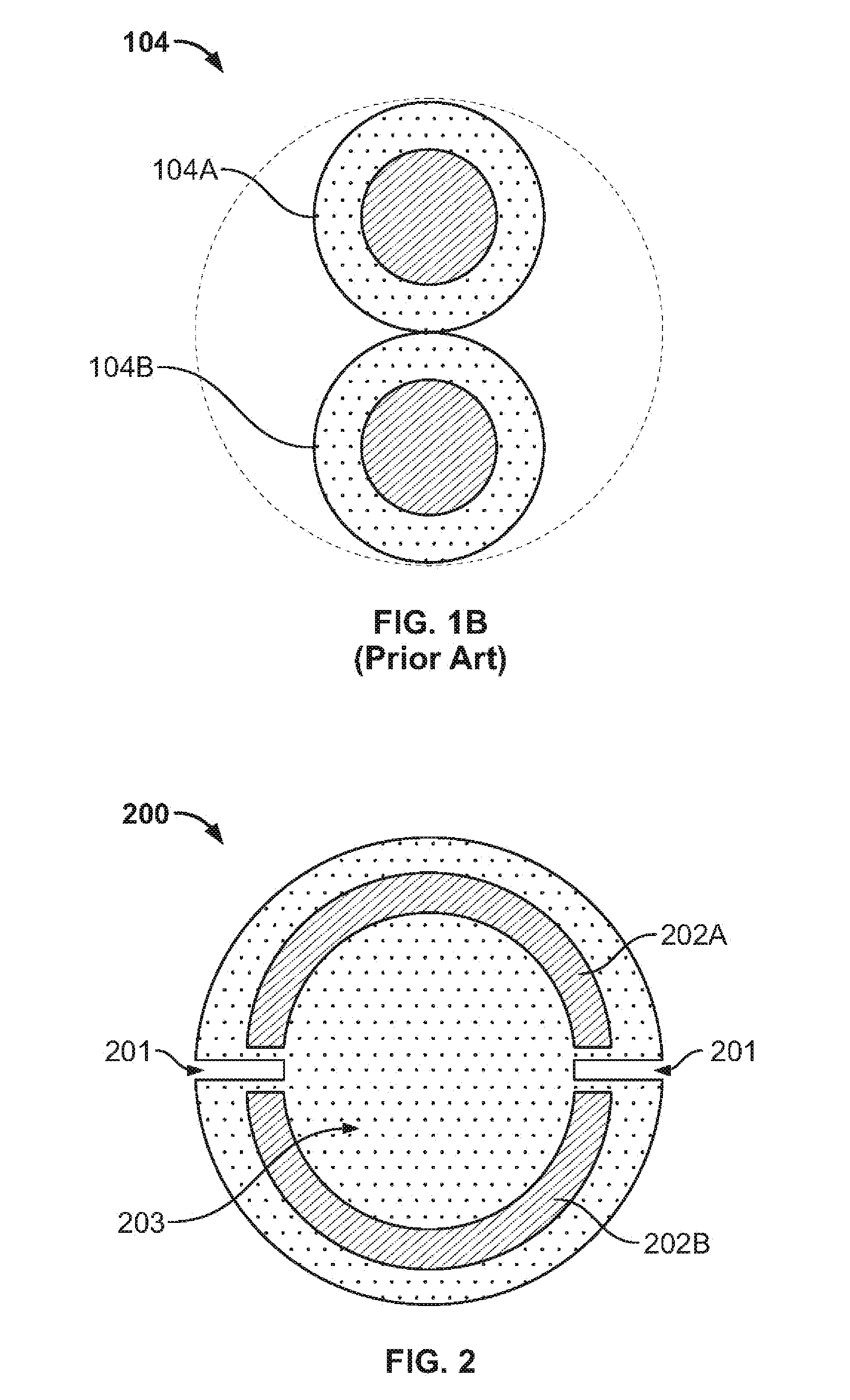
[0027] Embodiments of the present invention comprise a mirrored arc geometrical arrangement of two conductors configured to perform similar functions as the traditional twisted pair of wires. In one embodiment, a mirrored arc conductor pair occupies the same physical space required by prior art twisted pair cable designs. The mirrored arc configuration of the present invention provides self-shielding without the need for an overall metal shield.

[0028] In addition, the size of each insulated conductor of ...


PUM

PropertyMeasurementUnit
non-conductingaaaaaaaaaa
dielectricaaaaaaaaaa
perimeteraaaaaaaaaa

Abstract

A mirrored arc geometrical arrangement of two conductors configured to perform similar functions as a traditional twisted pair of wires is presented. The mirrored arc conductor pair occupies the same physical space required by prior art twisted pair cable designs. Each conductor pair includes two inward-facing arc shaped conductors placed within a dielectric material. Each arc shaped conductor may be constructed from thin foil strips of a conducting metal or from a group of separate bare metal conductors which are placed side by side in intimate contact so as to effectively create the same mirrored arc geometry. The conductor pairs may subsequently be bundled to create a data network cable bundle.

Description

CROSS REFERENCE TO RELATED APPLICATIONS [0001] This application claims priority from U.S. Provisional Patent Application Ser. No. 60 / 734,796, filed on Nov. 07, 2005, specification and drawings of which are herein incorporated by reference.FIELD OF INVENTION [0002] This invention relates to the field of signal transmission. More specifically, invention relates to a cable for transmission of data and video. BACKGROUND OF INVENTION [0003] Unshielded twisted pair (UTP) cable is popular for analog and digital data transmission. It consists of a multiplicity of twisted pair wires arranged in a specific grouping—typically four pairs to a jacketed bundle (see FIG. 1A). [0004]FIGS. 1A and 1B illustrate prior art Unshielded Twisted Pair (UTP) cable for data transmission. As illustrated in FIG. 1A, a typical UTP cable 100 comprises four twisted pair wires 104, 106, 108, and 110, all located within a cable bundle. The bundled twisted pair wires are held together with insulation layer 102. Each ...

Claims


Application Information

Patent Timeline
Patent Type & Authority Applications(United States)
IPC IPC(8): H01B11/06
CPCH01B7/0018H01B11/002
Inventor SOMERS, STEVE
Owner RGB SYST INC
Why Eureka
Try Eureka