Multi-band antenna

a multi-band antenna and antenna technology, applied in the field of antennas, can solve problems such as system occurring self-excitation

Inactive Publication Date: 2007-05-31
HON HAI PRECISION IND CO LTD
View PDF6 Cites 37 Cited by
  • Summary
  • Abstract
  • Description
  • Claims
  • Application Information

AI Technical Summary

Benefits of technology

[0011] A primary object, therefore, of the present invention is to provide a multi-band antenna which can avoid self-excitation and fetch up radiating blind field.

Problems solved by technology

However, because the two PIFAs are mirror image arranged, a pair of radiating element ends of providing common frequency are mirror image arranged too, the PIFA system cannot distinguish which PIFA being a primary antenna and which being a secondary antenna, thus making the PIFA system occurring self-excitation.

Method used


Image

  • Multi-band antenna
  • Multi-band antenna
  • Multi-band antenna

Examples


Embodiment Construction

[0016] Reference will now be made in detail to a preferred embodiment of the present invention.

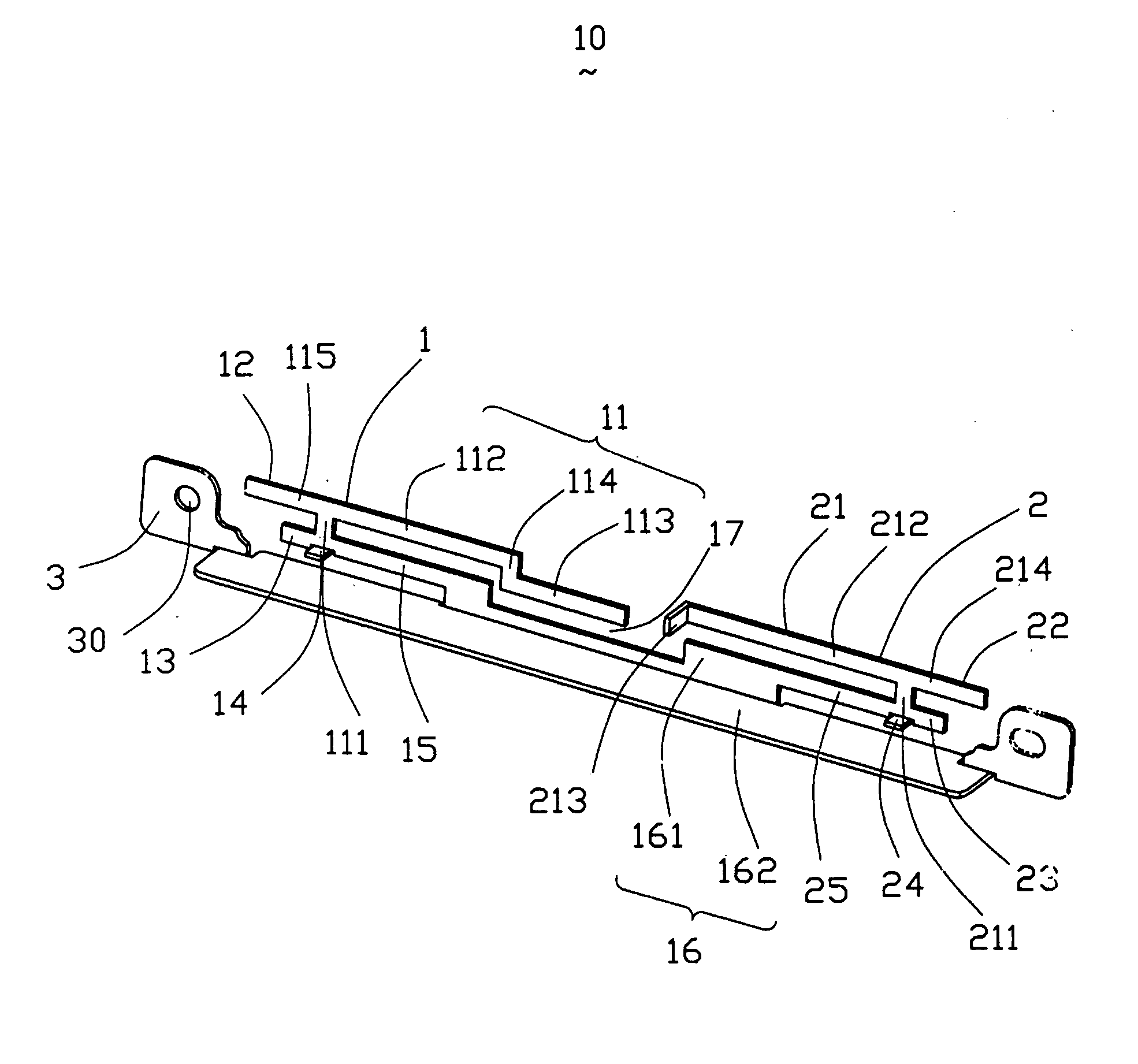
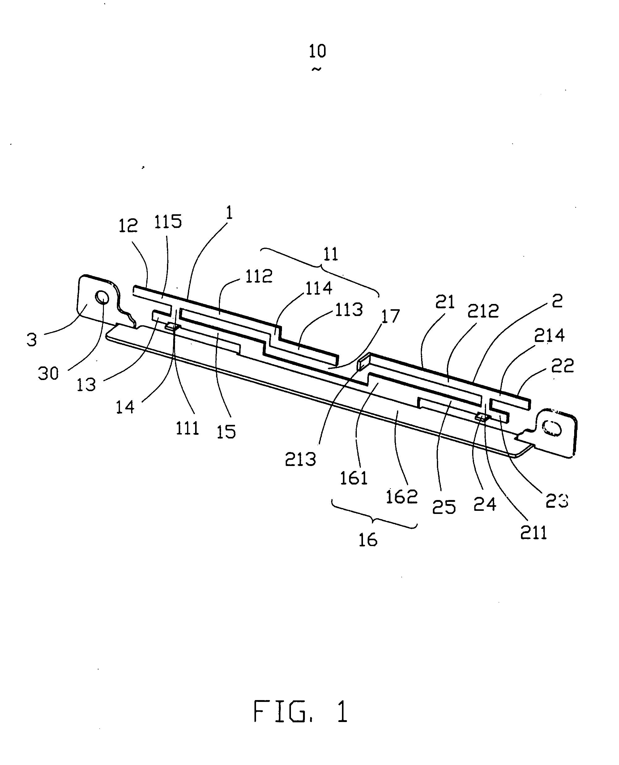
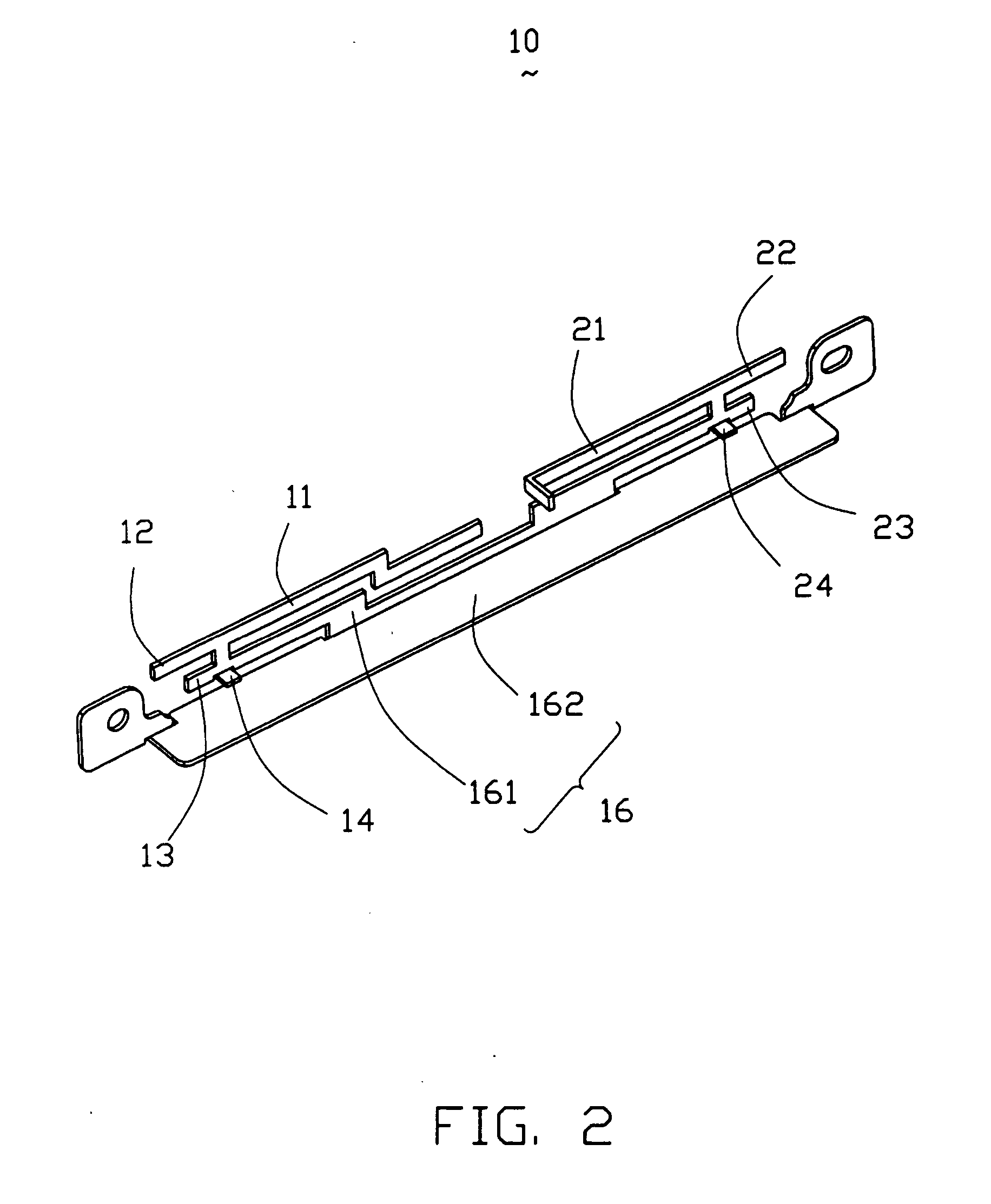
[0017] Referring to FIG. 1 and FIG. 2, a multi-band antenna 10 according to the preferred embodiment of the present invention is stamped and bent from a metal patch. The multi-band antenna 10 comprises a first antenna 1 and a second antenna. The first antenna 1 comprises a first radiating element 11, a second radiating element 12, a third radiating element 13, a first feeding cap 14, a first connecting element 15, a grounding element 16, and a first feeding line (not shown). The first radiating element 11 operates at 2.4 GHz of lower frequency band of IEEE802.1 a standard. The second radiating element 12 operates at 5 GHz of higher frequency band of IEEE802.11b / g. The third radiating element 13 is complementarity to the second radiating element 12 and enhances frequency band of the higher frequency. The second antenna 2 comprises a first radiating portion 21, a second radiating portion 22...


PUM


Abstract

A multi-band antenna adapted for used in a portable electronic device, includes: a first antenna including a first radiating element, a common grounding element, and a first connecting element connecting the first radiating element and the common grounding element; a second antenna, including a first radiating portion, the common grounding element, and a second connecting element connecting the radiating portion and the grounding element. Free end portions of the first radiating element and the first radiating portion do not align with each other in any direction.

Description

BACKGROUND OF THE INVENTION [0001] 1. Field of the Invention [0002] The present invention relates generally to an antenna, and more particularly to a multi-band antenna used in a portable electronic device, such as a notebook. [0003] 2. Description of the Prior Art [0004] With the development of wireless communication, more and more people hope to own portable electronic devices, such as a notebook, capable of connecting to Internet. The systems of the WLAN (Wireless Local-area Network) and the GPRS (General Packer Radio Service) can make the portable electronic devices, such as a notebook, work in Internet. The GPRS is a wide-area network and the data transfer speed thereof is 30 Kbps˜50 Kbps. The WLAN is a local-area network and the data transfer speed is 1 Mbps. The portable electronic device, such as a notebook can choose different Wireless cards for jointing to Internet. [0005] At present, the WLAN is based on Bluetooth technology standard or IEEE802.11 series technology standa...

Claims


Application Information

Patent Timeline
Patent Type & Authority Applications(United States)
IPC IPC(8): H01Q1/24
CPCH01Q1/243H01Q9/42H01Q5/40H01Q5/371H01Q21/28
Inventor HUNG, CHEN-TAWANG, SHU-YEANKE, YUN-LONG
Owner HON HAI PRECISION IND CO LTD
Why Eureka
Try Eureka