Loop antenna attached to rear window of vehicle

a technology for loop antennas and rear windows, which is applied in the direction of antennas, antenna details, antenna adaptation in movable bodies, etc., can solve the problems of affecting affecting the appearance, and difficult mounting of sheet antennas there, so as to achieve the effect of not impairing the performance of loop antennas

Inactive Publication Date: 2007-05-31
FUJITSU GENERAL LTD
View PDF4 Cites 21 Cited by
  • Summary
  • Abstract
  • Description
  • Claims
  • Application Information

AI Technical Summary

Benefits of technology

[0022] As explained above, the loop antenna of the present invention can be installed at the rear window of a vehicle, so does not detract from the appearance of the vehicle. Further, according to the method of mounting a loop antenna to a vehicle of the present invention, a film shaped antenna

Problems solved by technology

This makes mounting a sheet-like antenna there difficult.
However, a pole antenna installed at the rear body of a vehicle or the rear window sticks out from the body of the chassis, so ruins the appearance and therefore is not preferable design wise.
Further, even if tryi

Method used


Image

  • Loop antenna attached to rear window of vehicle
  • Loop antenna attached to rear window of vehicle
  • Loop antenna attached to rear window of vehicle

Examples


second embodiment

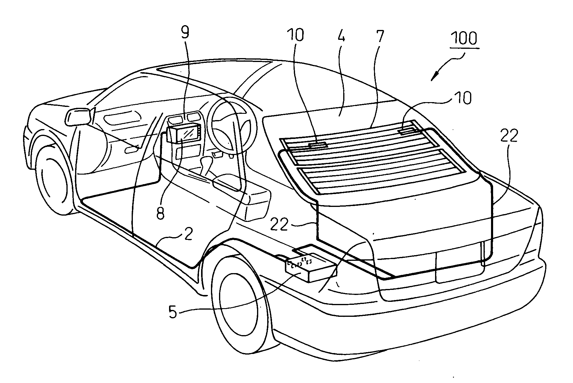
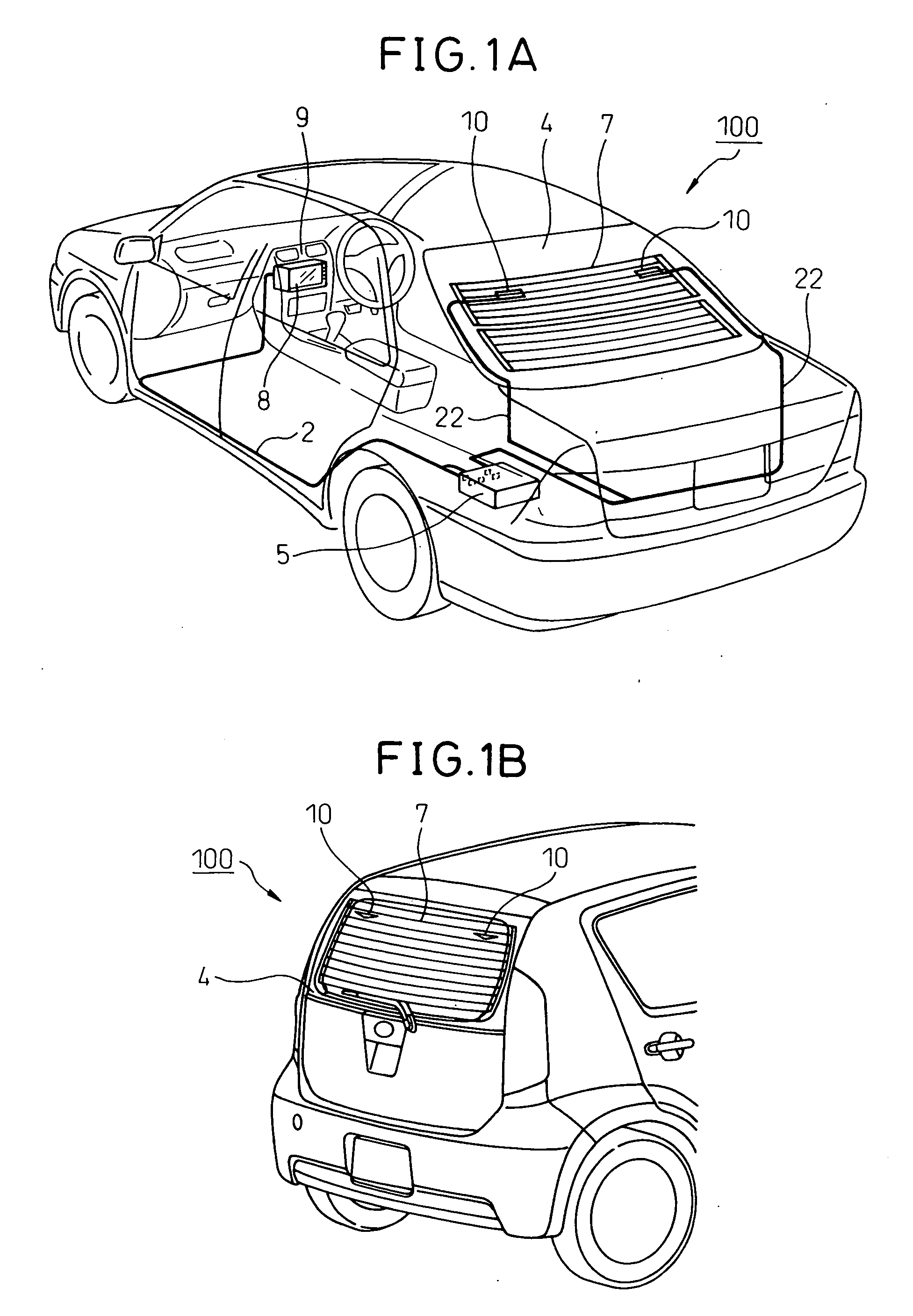
[0066] The loop antennas of the present invention 10 are provided at regions of the rear window 4 of the automobile 100 where a defogger 7 is provided and, for example, receive a terrestrial wave digital TV broadcast. Here, the loops are rectangular in shape. Loop antennas 10 of a second embodiment explained later are shown. The loop antennas 10 of this example are arranged straddling electrical heating wires of the defogger 7 and are connected to the TV tuner 5 installed under the rear seat of the automobile 100 etc. by coaxial cables 22. Further, the signal (image) received by the TV tuner 5 is input to the navigation system 8 provided at the instrument panel 9 by a cable 2, whereby the navigation system 8 displays the received image at its display device in the TV mode.

first embodiment

[0067]FIG. 1B shows another example of installation of loop antennas 10 according to an embodiment of the present invention in an automobile. In this example, loop antennas 10 are provided at the rear window 4 of a hatchback type automobile 100 where a defogger 7 is provided. This figure shows loop antennas of a first embodiment explained later. The loops are triangular in shape. In this way, the loop antennas of the present invention 10 are mainly provided at the rear window 4 of the automobile where the defogger 7 is provided.

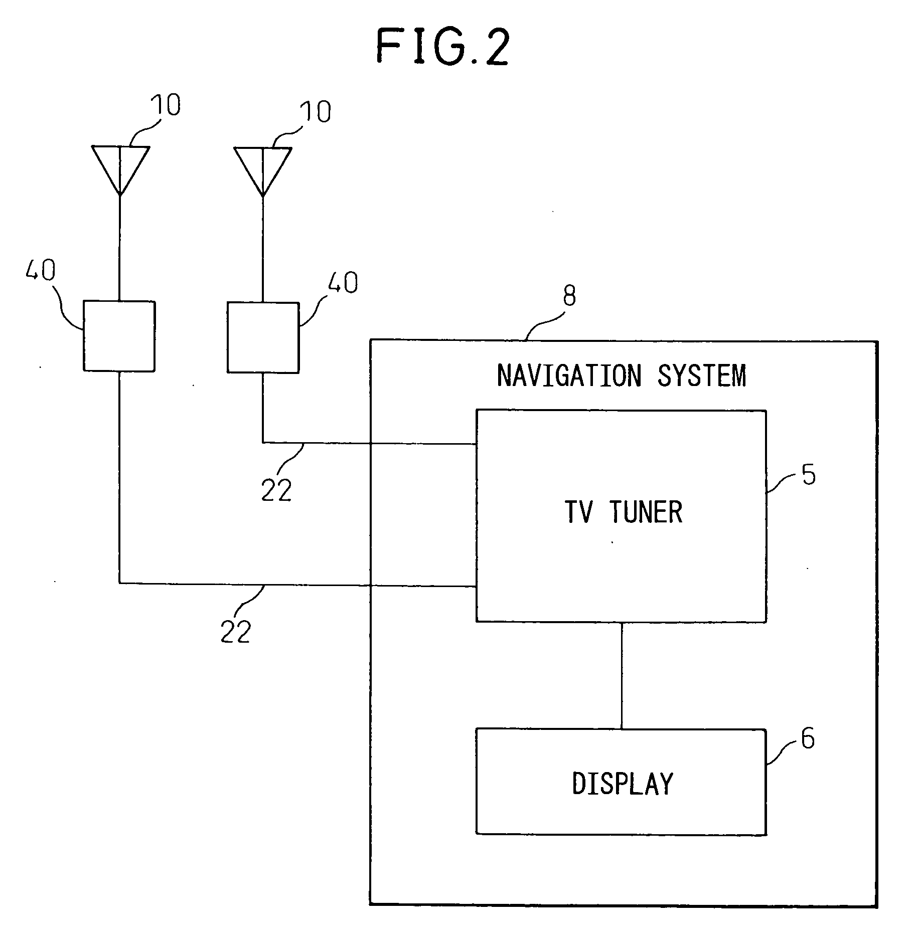
[0068]FIG. 2 is a block circuit diagram showing an example of the configuration of a navigation system 8 as a receiver using loop antennas 10 of the present invention. In the example shown in FIG. 1A, the TV tuner 5 was separate from the navigation system 8, but in this example, the TV tuner 5 is built into the navigation system 8. When the loop antennas 10 are antennas receiving a terrestrial digital TV wave, the signals received by the loop antennas 10 are ...

third embodiment

[0084] In this embodiment, the distance D1 from the bottom 71A of the one triangular shaped antenna element 71 to the two power feed terminals 91, 92, the length D2 of the straight elements 74, and the distance D3 from the bottom 71A of the other triangular shaped antenna element 71 to the vertex are the same lengths and are formed smaller than the distance between adjoining electrical heating wires of the defogger 7. Further, the loop antenna 13 of the third embodiment is mounted to the rear window so that the one triangular shaped antenna element 71 and the other triangular shaped antenna element 71 are provided in the region between the adjoining electrical heating wires of the defogger 7 and so that the straight elements 74 perpendicularly intersect the electrical heating wires of the defogger 7. The straight elements 74 and the electrical heating wires of the defogger 7 preferably perpendicularly intersect.

[0085] Further, the length D4 of the bottoms 71A should be made λ / 2 of t...


PUM


Abstract

A loop antenna able to be mounted on the rear window of a vehicle provided with a defogger, that is, a loop antenna to be mounted on a rear window provided with a defogger having electrodes arranged in the vertical direction at the two ends and a plurality of electrical heating wires bridging the electrodes in the horizontal direction, wherein an antenna element forming a loop is made polygonal in shape, two power feed terminals of the loop antenna are provided at positions a predetermined distance away from the midpoint of the bottom of the antenna element, constituted by one side, in the vertical direction, a distance between the power feed terminals and bottom is formed smaller than the distance between adjoining electrical heating wires of the defogger, and the loop antenna is mounted on the rear window between the adjoining electrical heating wires. The polygonal shape may be a triangular shape.

Description

CROSS-REFERENCE TO RELATED APPLICATIONS [0001] This application claims priority from, and incorporates by reference the entire disclosure of, Japanese Patent Application No. 2005-342891, filed on Nov. 28, 2005, and No. 2006-126652, filed on Apr. 28, 2006. BACKGROUND OF THE INVENTION [0002] 1. Field of the Invention [0003] The present invention relates to a loop antenna attached to a rear window of a vehicle, more particularly relates to a loop antenna able to be installed on the rear window of a vehicle provided with a defogger, a method of mounting a loop antenna on a rear window of a vehicle, and a rear window of a vehicle provided with a loop antenna. [0004] 2. Description of the Related Art [0005] Since the past, automobiles and other vehicles (moving bodies) have been equipped with antennas able to receive electromagnetic waves even during motion. The electromagnetic waves received by vehicles have for many years mainly been medium waves (MW) for AM radio use and very high freq...

Claims


Application Information

Patent Timeline
IPC IPC(8): H01Q1/32H01Q1/02
CPCH01Q1/1271H01Q7/00H01Q1/32
Inventor OGINO, KAZUSHIGEUMEZAWA, YOSHIOTSURUTA, KATSUHIROFUJIWARA, AKIHIRO
Owner FUJITSU GENERAL LTD
Why Eureka
Try Eureka